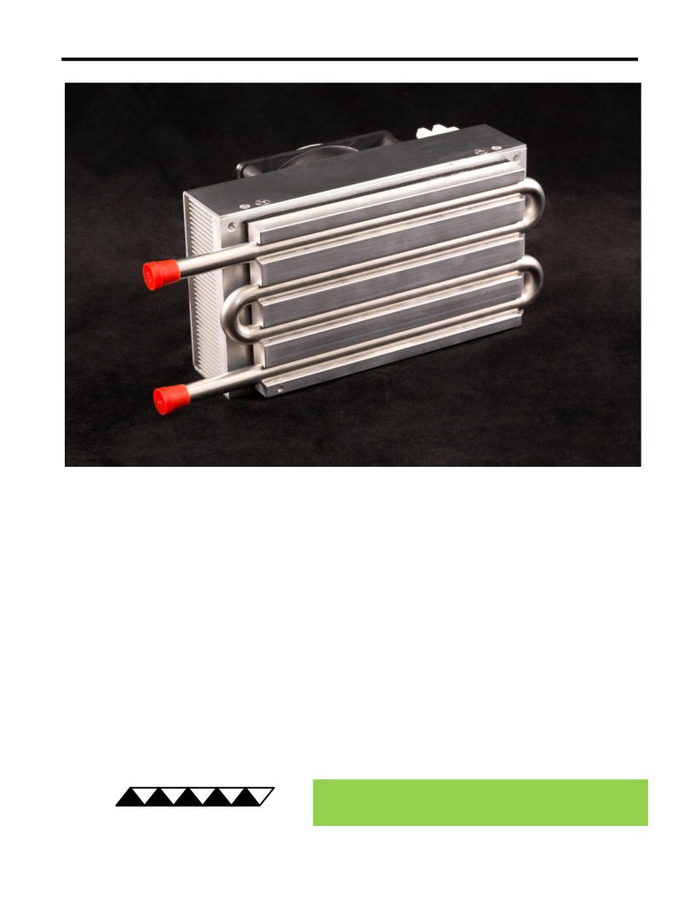
LC-066SS Peltier-Thermoelectric Liquid Cooler
• A compact, high-density extruded heat sink and a four-pass heat exchanger provides
good cooling capacity in a small size.
• The only wetted surface is 316 stainless steel tubing making the liquid exchanger
compatible with a wide variety of fluids.
• Two 316 stainless steel Mixer Coils can be easily added into the liquid tubing to
improve performance at low flow rates. Mixer Coils sold and installed separately.
• Useful for small-to-medium heat loads in medical products, laser diode coolers,
laboratory instruments, gas-stream dehumidification, etc.
• Heat-sink fan can be PWM controlled to reduce fan noise in low heat load conditions.
• Threaded hole located in liquid exchanger provides for easy attachment of a
temperature sensor.
• CE marked; RoHS compliant.
® Expert Engineering, Precision Manufacturing:
Quality Thermal Solutions Delivered
TE
TECHNOLOGY, INC.
NOTE: All specifications are subject to change without notice.
© 2020 TE Technology, Inc.
LC-066SS 03-MAR-2020 Page 1 of 10
Thermoelectric (TE) Power (typical)1 :
24 VDC at 4.4 A
NEMA Rating: NA
Thermoelectric (TE) Power (maximum)2 :
24 VDC at 5.5 A
LC-066SS
External (ambient) Fan Power:
24 VDC at 0.21 A
Specifications
Weight (kg):
1.52
External (ambient) Fan Noise:
43 dBA
Performance is based on unrestricted air flow to fan and
from air-flow outlets and 1.6 L/min water flow rate through
the liquid heat exchanger. Do not operate if the ambient,
liquid, heat sink, or liquid heat exchanger temperatures
information before purchasing or using this product.
exceed 70 °C. Do not operate at air temperatures below
-20 °C. Do not freeze the liquid. Do not exceed 1034 kPa
water pressure.
1Current, at steady state, is rated at +25 °C ambient, +25 °C inlet water, maximum heat removal. At 5 °C inlet, the typical steady-state current is 4.25 A.
2Current, at steady-state operation under-worst case conditions, is rated at -10 °C ambient, +70 °C inlet, maximum heat removal.
RoHS Compliant
Directive 2011/65/EU
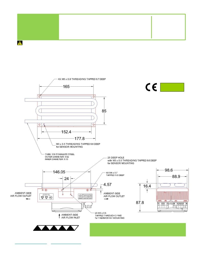
A 3D PDF, STEP, and Parasolid solid
models are also available from the website.
All dimensions in millimeters.
Liquid heat exchanger side shown in blue;
External (ambient) side shown in red.
® Expert Engineering, Precision Manufacturing:
Quality Thermal Solutions Delivered
TE
TECHNOLOGY, INC.
NOTE: All specifications are subject to change without notice.
© 2020 TE Technology, Inc.
LC-066SS 03-MAR-2020 Page 2 of 10
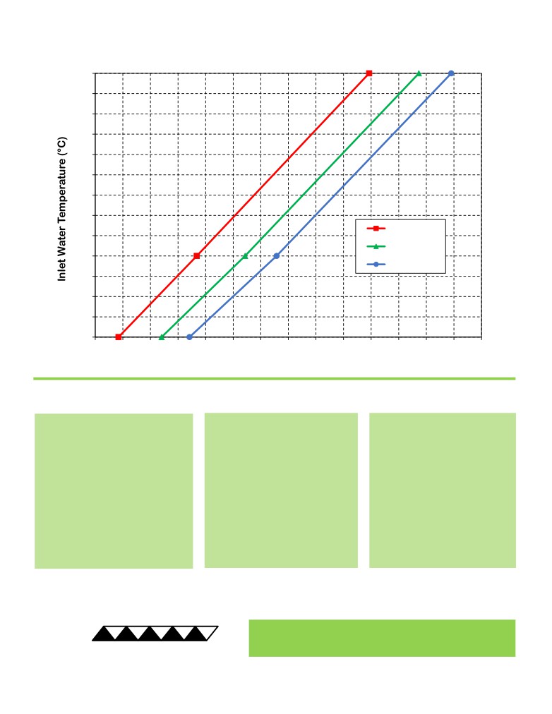
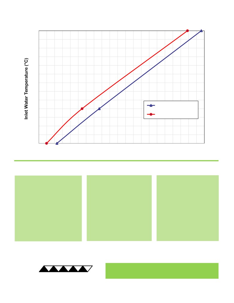
LC-066SS Cooling Performance Graph
(removing heat from water, flowing at 1.6 L/min)
70
65
60
55
50
45
40
35
50 °C ambient
30
35 °C ambient
25
25 °C ambient
20
15
10
5
0
10
20
30
40
50
60
70
80
90
100
110
120
130
140
Heat Removed from Water (watts)
How to use the Performance Graph:
1. Select Performance Line
2. Select Enclosure Temperature
3. Determine Cooling Capacity
The diagonal lines represent cooling
Draw a horizontal line on the graph
The maximum amount of heat
performance at the indicated ambient
corresponding to the desired inlet
that the cooler can remove from
air temperature (inlet temperature to
water temperature until it intersects
the water is determined by the
the ambient-side heat sink). If the
with the performance line
intersection point (determined in
cooler is to operate at a different
corresponding to the ambient
the previous step). The cooler will
ambient, then you must sketch in a
temperature at which the cooler is to
be able to maintain the desired
new performance line. This can be
operate.
water temperature if the cooling
drawn parallel to one of the existing
capacity exceeds the heat load. If
lines, using the distance between the
the heat load exceeds the cooling
existing lines as a scale to properly
capacity then a higher capacity
locate the new line.
cooler will be needed.
Example: You need to maintain the water at 15 °C while in a 25 °C ambient. The cooler can remove a maximum of
approximately 50 W of heat from the water. If the heat load (internally generated heat plus the heat gain through
insulation, solar, vapor condensation, etc.) in the system exceeds this, you would need more coolers and/or a larger
cooler.
® Expert Engineering, Precision Manufacturing:
Quality Thermal Solutions Delivered
TE
TECHNOLOGY, INC.
NOTE: All specifications are subject to change without notice.
© 2020 TE Technology, Inc.
LC-066SS 03-MAR-2020 Page 3 of 10
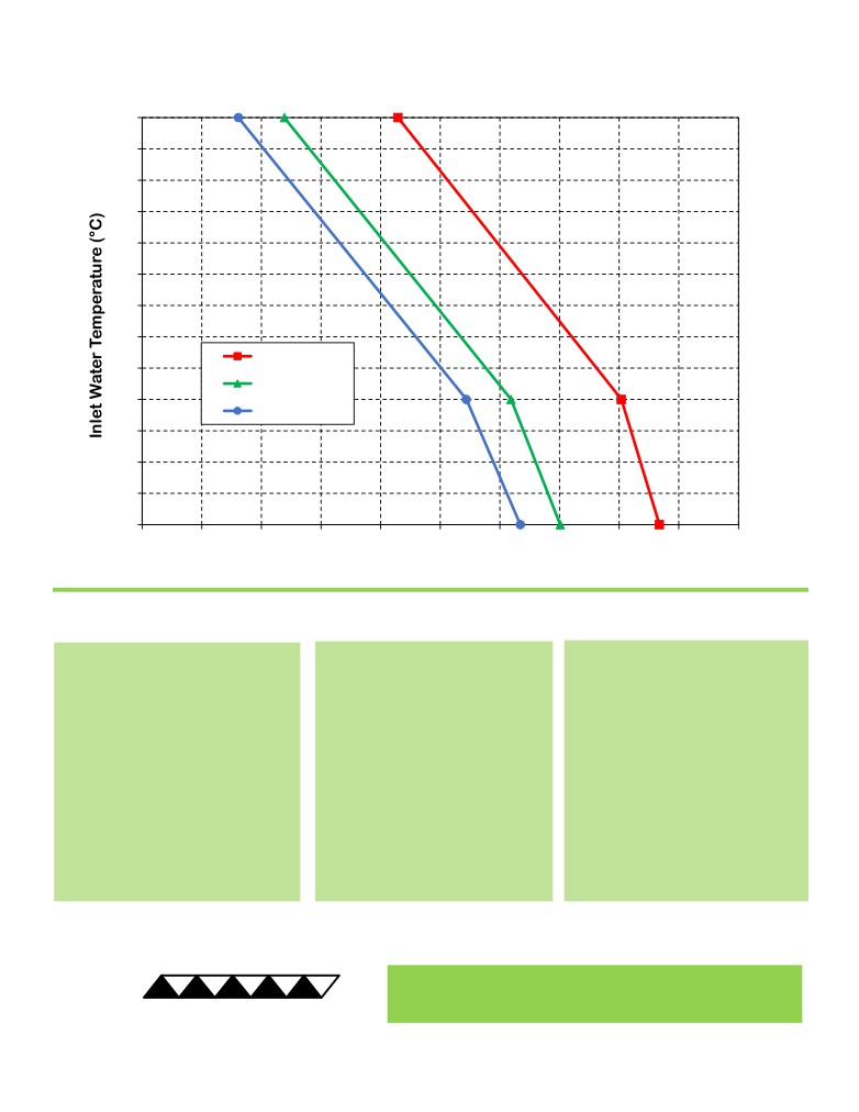
LC-066SS Heating Performance Graph
(adding heat to water, flowing at 1.6 L/min)
70
65
60
55
50
45
40
35
25 °C ambient
30
0 °C ambient
25
-10 °C ambient
20
15
10
5
0
20
40
60
80
100
120
140
160
180
200
Heat Added to Water (watts)
How to use the Performance Graph:
1. Select Performance Line
2. Select Enclosure Temperature
3. Determine Heating Capacity
The diagonal lines represent heating
Draw a horizontal line on the graph
The maximum amount of heat that
performance at the indicated ambient
corresponding to the desired inlet
the cooler can add to the water is
air temperature (inlet temperature to
water temperature of the enclosure.
determined by the intersection point
the ambient-side heat sink). If the
Make the line intersect with the
(determined in previous step). If the
cooler is to operate at a different
performance line corresponding to
heat added to the water (including
ambient, then you must sketch in a
the ambient temperature at which
heat generated by the system) is
new performance line. This can be
the cooler is to operate.
greater than the system’s heat loss,
drawn parallel to one of the existing
then the cooler will be able to heat to
lines, using the distance between the
the desired temperature. A higher
existing lines as a scale to properly
capacity cooler will be needed if the
locate the new line.
total heat added is less than the
system’s heat loss.
Example: You need to maintain the water at 30 °C while in a -10 °C ambient. The cooler can add a maximum of
approximately 100 W of heat to the water. If the heat dissipation from the system exceeds this, you would need more
coolers and/or a larger cooler.
® Expert Engineering, Precision Manufacturing:
Quality Thermal Solutions Delivered
TE
TECHNOLOGY, INC.
NOTE: All specifications are subject to change without notice.
© 2020 TE Technology, Inc.
LC-066SS 03-MAR-2020 Page 4 of 10
LC-066SS with Two Mixer Coils Installed
(removing heat from water, flowing at 0.5 L/min; Mixer Coils sold separately)
70
65
60
55
50
45
40
35
30
0.5 L/min, with mixer coils
25
0.5 L/min, no mixer coils
20
15
10
5
25
30
35
40
45
50
55
60
65
70
75
80
85
90
95
100 105 110 115 120 125
130
Heat Removed from Water (watts)
How to use the Performance Graph:
1. Select Performance Line
2. Select Enclosure Temperature
3. Determine Cooling Capacity
The diagonal lines represent cooling
Draw a horizontal line on the graph
The maximum amount of heat
performance at the indicated ambient
corresponding to the desired inlet
that the cooler can remove from
air temperature (inlet temperature to
water temperature until it intersects
the water is determined by the
the ambient-side heat sink). If the
with the performance line
intersection point (determined in
cooler is to operate at a different
corresponding to the ambient
the previous step). The cooler will
ambient, then you must sketch in a
temperature at which the cooler is to
be able to maintain the desired
new performance line. This can be
operate.
water temperature if the cooling
drawn parallel to one of the existing
capacity exceeds the heat load. If
lines, using the distance between the
the heat load exceeds the cooling
existing lines as a scale to properly
capacity then a higher capacity
locate the new line.
cooler will be needed.
Example: You need to maintain the water at 15 °C while in a 25 °C ambient. The cooler can remove a maximum of
approximately 54 W of heat from the water. If the heat load (internally generated heat plus the heat gain through
insulation, solar, vapor condensation, etc.) in the system exceeds this, you would need more coolers and/or a larger
cooler.
® Expert Engineering, Precision Manufacturing:
Quality Thermal Solutions Delivered
TE
TECHNOLOGY, INC.
NOTE: All specifications are subject to change without notice.
© 2020 TE Technology, Inc.
LC-066SS 03-MAR-2020 Page 5 of 10
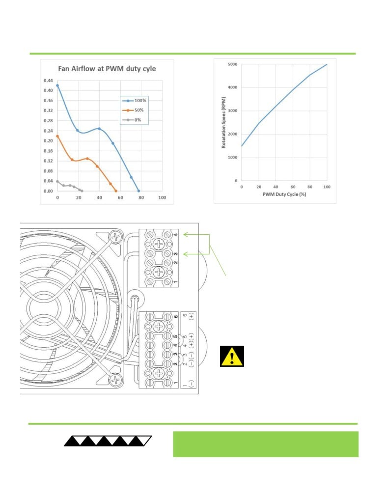
LC-066SS External Fan Connections
The external fan speed can be optionally
controlled using pulse width modulation at a
recommended
5
kHz to
25
kHz frequency
applied at terminal position 4 (SPD CTRL, brown
wire). The TC-720 temperature controller can be
used to provide this PWM signal to reduce the
audible noise at low cooling demands
(use
5400Hz frequency setting). Electrical ground to
terminal position 4 will reduce fan speed.
Terminal position
3 provides for a fan-speed
sensor, sending
two pulses per revolution.
Consult with TE Technology if you wish to use
this feature.
STRIP WIRE ENDS
7.6
mm (0.30
in),
INSTALL WIRES
(22-12
AWG), TIGHTEN
SCREWS TO 0.56 N-m (5 lbs-in).
NOTE: Do not apply solder (tin) to the ends of
the wires before inserting them into the
connector. This will generate excessive heat
at the terminal resulting in latent failures. Use
copper wire only.
Do not allow heat sink temperature to exceed
maximum limit when operating at low fan
speeds.
Expert Engineering, Precision Manufacturing:
®
Quality Thermal Solutions Delivered
TE
TECHNOLOGY, INC.
NOTE: All specifications are subject to change without notice.
© 2020 TE Technology, Inc.
LC-066SS 03-MAR-2020 Page 6 of 10
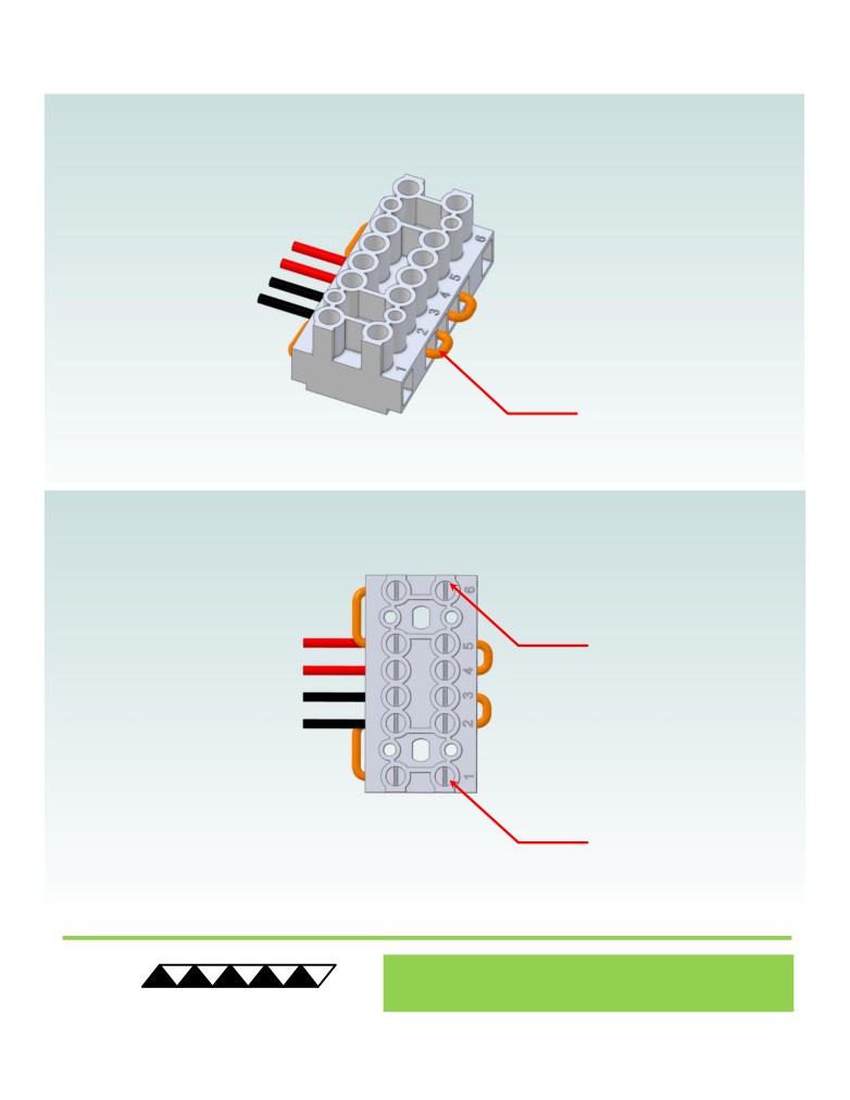
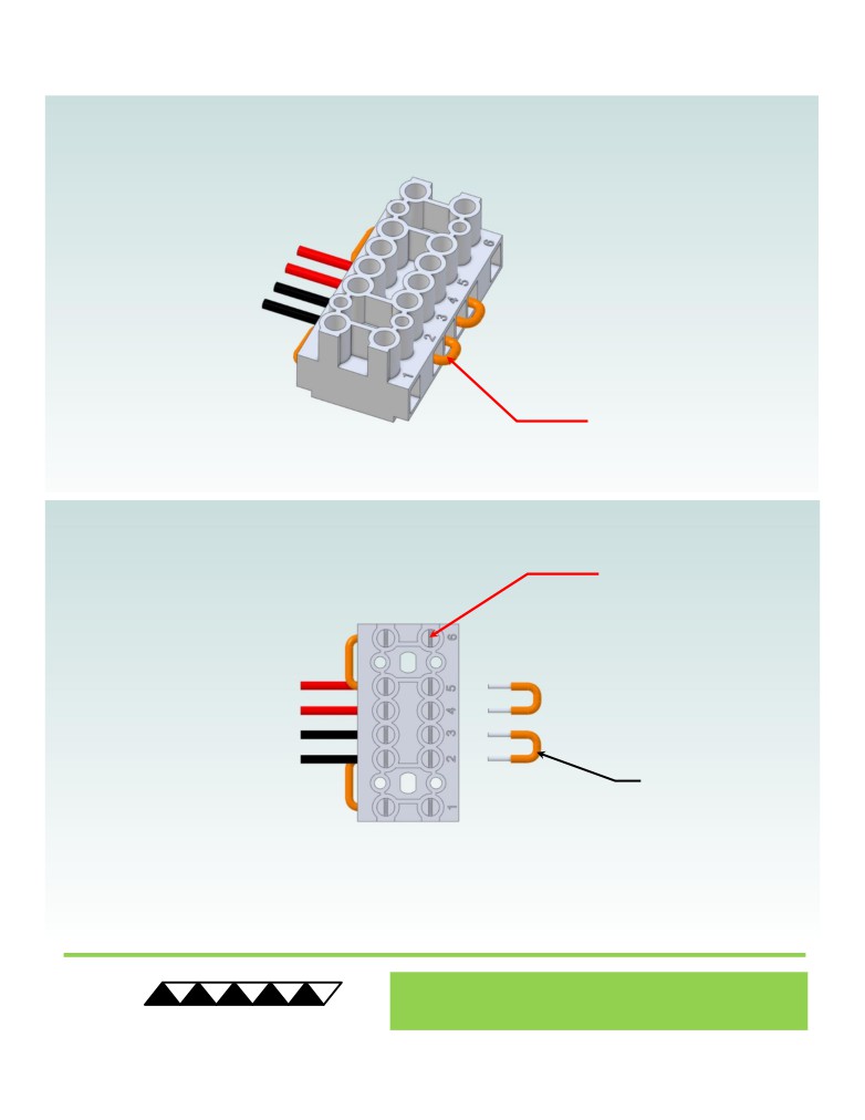
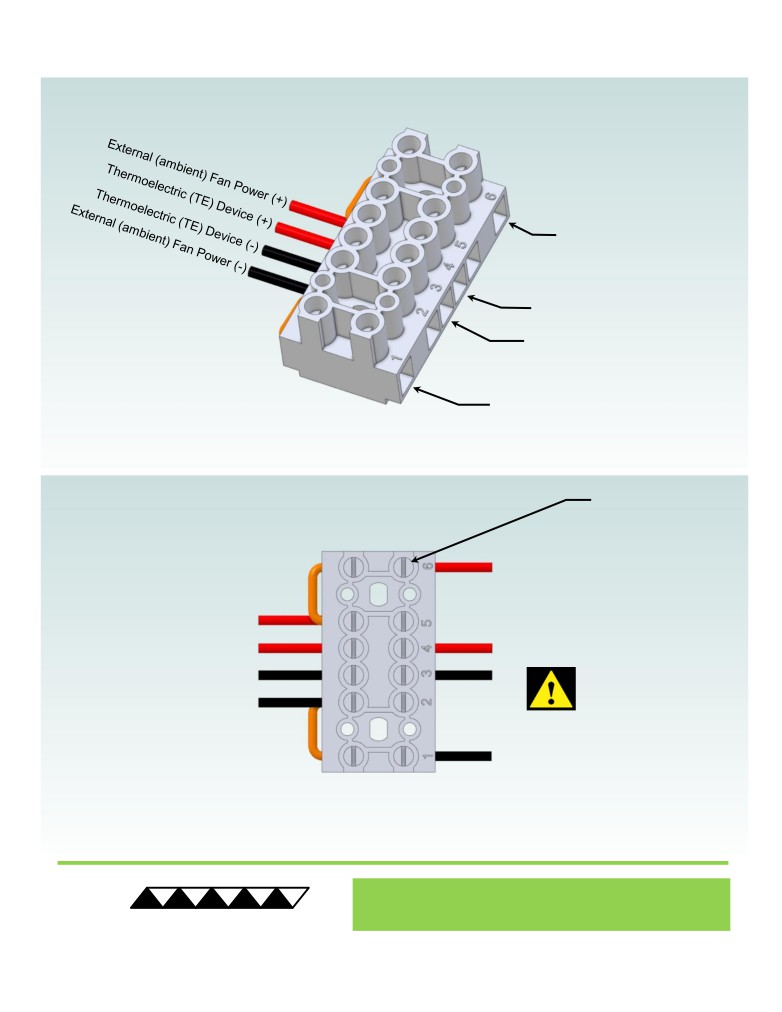
Terminal Block Configuration for Continuous Operation at Full Power
As-Shipped Configuration 1 of 2
1
ELECTRICAL
JUMPERS, SHOWN IN
ORANGE, INSTALLED
(ORIGINAL
CONFIGURATION)
2
LOOSEN SCREW BUT
DO NOT REMOVE
LOOSEN SCREW BUT
DO NOT REMOVE
® Expert Engineering, Precision Manufacturing:
Quality Thermal Solutions Delivered
TE
TECHNOLOGY, INC.
NOTE: All specifications are subject to change without notice.
© 2020 TE Technology, Inc.
LC-066SS 03-MAR-2020 Page 7 of 10
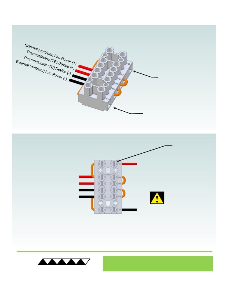
Terminal Block Configuration for Continuous Operation at Full Power
2 of 2
3
Power supply (+) Red Wire
to POSITION 6
Power supply (-) Black Wire
to POSITION 1
STRIP WIRE ENDS
4
7.6 mm (0.30 in),
INSTALL WIRES (22-
12 AWG),
TIGHTEN SCREWS
TO 0.56 N-m (5 lbs-in)
NOTE: Do not apply solder (tin)
to the ends of the wires before
inserting them into the
connector. This will generate
excessive heat at the terminal
resulting in latent failures. Use
copper wire only.
® Expert Engineering, Precision Manufacturing:
Quality Thermal Solutions Delivered
TE
TECHNOLOGY, INC.
NOTE: All specifications are subject to change without notice.
© 2020 TE Technology, Inc.
LC-066SS 03-MAR-2020 Page 8 of 10
Terminal Block Configuration for Operation with Temperature Controller
1 of 2
1
ELECTRICAL
JUMPERS, SHOWN IN
ORANGE, INSTALLED
(ORIGINAL
CONFIGURATION)
2
LOOSEN SCREWS
BUT DO NOT
REMOVE
REMOVE TWO
ELECTRICAL JUMPERS
FROM 2-3 AND 4-5
® Expert Engineering, Precision Manufacturing:
Quality Thermal Solutions Delivered
TE
TECHNOLOGY, INC.
NOTE: All specifications are subject to change without notice.
© 2020 TE Technology, Inc.
LC-066SS 03-MAR-2020 Page 9 of 10
Terminal Block Configuration for Operation with Temperature Controller
2 of 2
3
Power supply (+) Red Wire
to POSITION 6
Temperature Controller (+) Red Wire
to POSITION 4
Temperature Controller (-) Black Wire
To POSITION 3
Power supply (-) Black Wire
to POSITION 1
STRIP WIRE ENDS
4
7.6 mm (0.30 in),
INSTALL WIRES (22-
12 AWG),
TIGHTEN SCREWS
TO 0.56 N-m (5 lbs-in)
NOTE: Do not apply solder (tin)
to the ends of the wires before
inserting them into the
connector. This will generate
excessive heat at the terminal
resulting in latent failures. Use
copper wire only.
® Expert Engineering, Precision Manufacturing:
Quality Thermal Solutions Delivered
TE
TECHNOLOGY, INC.
NOTE: All specifications are subject to change without notice.
© 2020 TE Technology, Inc.
LC-066SS 03-MAR-2020 Page 10 of 10