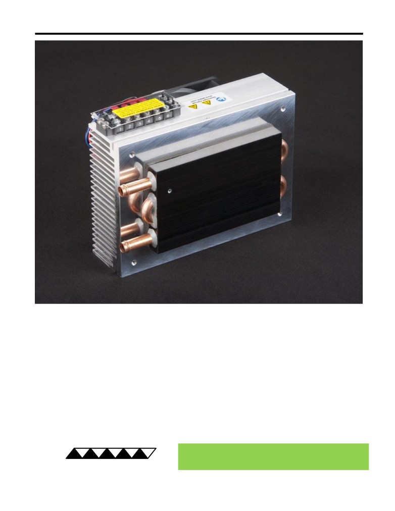
LC-061 Peltier-Thermoelectric Liquid Cooler
• A high-density extruded heat sink and a four-pass liquid exchanger provides good
cooling capacity for relatively small size.
• Useful for small-to-medium heat loads in medical products, laser diode coolers,
laboratory instruments, gas-stream dehumidification, etc.
• For production sized orders, the cooler may be customized with swirl inserts in the
liquid loops to improve heat transfer at low flow rates.
• Threaded hole located in liquid exchanger provides for easy attachment of a
temperature sensor.
• The cooler can easily be customized for production-sized orders to meet your exact
requirements.
• CE marked, RoHS compliant.
® Expert Engineering, Precision Manufacturing:
Quality Thermal Solutions Delivered
TE
TECHNOLOGY, INC.
NOTE: All specifications are subject to change without notice.
© 2019 TE Technology, Inc.
LC-061 26-DEC-2019 Page 1 of 8
Thermoelectric (TE) Power (typical)1 :
24 VDC at 4.5 A
NEMA Rating: NA
Thermoelectric (TE) Power (maximum)2 :
24 VDC at 5.5 A
LC-061
External (ambient) Fan Power:
24 VDC at 0.21 A
Specifications
Weight (kg):
2.0
External (ambient) Fan Noise:
44 dBA
Performance is based on unrestricted air flow to fan and
from air-flow outlets and 1.6 L/min water flow rate through
the liquid heat exchanger. Do not operate if the ambient,
liquid, heat sink, or liquid heat exchanger temperatures
information before purchasing or using this product.
exceed 70 °C. Do not operate at air temperatures below
-20 °C. Do not freeze the liquid. Do not exceed 205 kPa
water pressure.
1Current, at steady state, is rated at +25 °C ambient, +25 °C inlet water, maximum heat removal. At 5 °C inlet, the typical steady-state current is 4.4 A.
2Current, at steady-state operation under-worst case conditions, is rated at -10 °C ambient, +70 °C inlet, maximum heat removal.
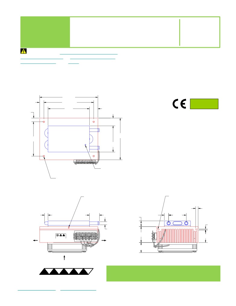
177.8
RoHS Compliant
12.7
152.4
Directive 2011/65/EU
127
25.4
11.2
23.5
A 3D PDF, .stp, and .sldprt solid models
are also available from the website. Contact
TE Technology for 3D solid models in other
127
104.6
formats.
80
All dimensions in millimeters.
Liquid heat exchanger side shown in blue;
External (ambient) side shown in red.
M3 x 0.5 THREADING TAPPED 9.7 DEEP
for SENSOR MOUNTING
4X M5 x 0.8 THREADING TAPPED 9.7 DEEP
25 DEEP HOLE
THREAD BOSS CAN BE USED
with M3 x 0.5 THREADING TAPPED 9.7 DEEP
FOR MOUNTING
for SENSOR MOUNTING
7.6
10.4
30.2
13.2
53.9
17.4
3
Ø9.5
AMBIENT-SIDE
AMBIENT-SIDE
48.5
Download manual
38.4
AIR FLOW OUTLET
AIR FLOW OUTLET
31
AMBIENT-SIDE
AIR FLOW INLET
® Expert Engineering, Precision Manufacturing:
Quality Thermal Solutions Delivered
TE
TECHNOLOGY, INC.
NOTE: All specifications are subject to change without notice.
© 2019 TE Technology, Inc.
LC-061 26-DEC-2019 Page 2 of 8
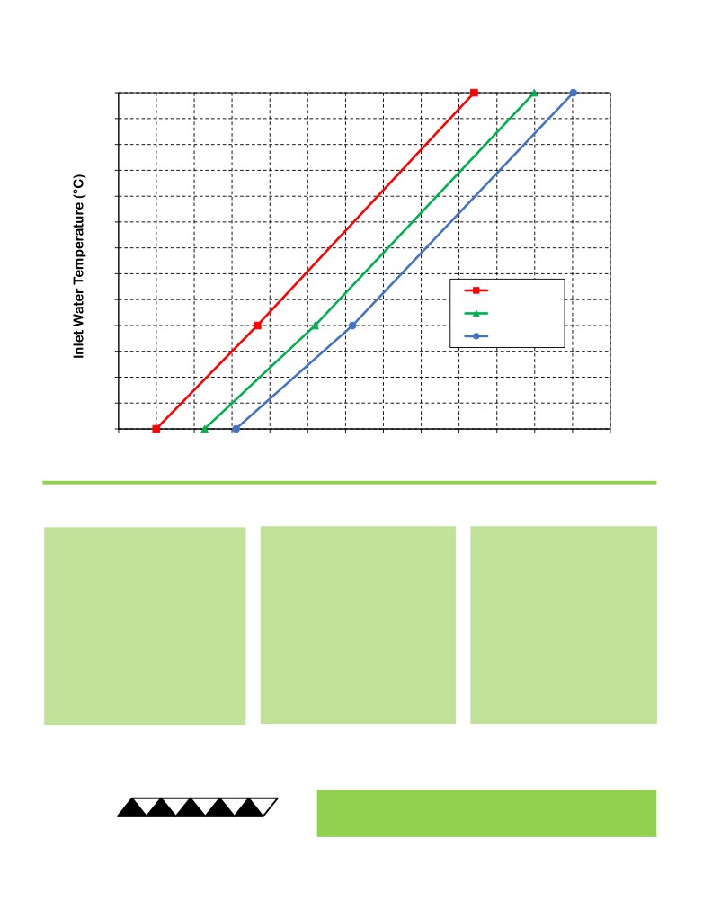
LC-061 Cooling Performance Graph
(removing heat from water, flowing at 1.6 L/min)
70
65
60
55
50
45
40
35
50 °C ambient
30
35 °C ambient
25
25 °C ambient
20
15
10
5
0
10
20
30
40
50
60
70
80
90
100
110
120
130
Heat Removed from Water (watts)
How to use the Performance Graph:
1. Select Performance Line
2. Select Enclosure Temperature
3. Determine Cooling Capacity
The diagonal lines represent cooling
Draw a horizontal line on the graph
The maximum amount of heat
performance at the indicated ambient
corresponding to the desired inlet
that the cooler can remove from
air temperature (inlet temperature on
water temperature until it intersects
the water is determined by the
the ambient-side fan). If the cooler is
with the performance line
intersection point (determined in
to operate at a different ambient,
corresponding to the ambient
the previous step). The cooler will
then you must sketch in a new
temperature at which the cooler is to
be able to maintain the desired
performance line. This can be drawn
operate.
water temperature if the cooling
parallel to one of the existing lines,
capacity exceeds the heat load. If
using the distance between the
the heat load exceeds the cooling
existing lines as a scale to properly
capacity then a higher capacity
locate the new line.
cooler will be needed.
Example: You need to maintain the water at 15 °C while in a 25 °C ambient. The cooler can remove a maximum of
approximately 52 W of heat from the water. If the heat load (internally generated heat plus the heat gain through
insulation, solar, vapor condensation, etc.) in the enclosure exceeds this, you would need more coolers and/or a larger
cooler.
® Expert Engineering, Precision Manufacturing:
Quality Thermal Solutions Delivered
TE
TECHNOLOGY, INC.
NOTE: All specifications are subject to change without notice.
© 2019 TE Technology, Inc.
LC-061 26-DEC-2019 Page 3 of 8
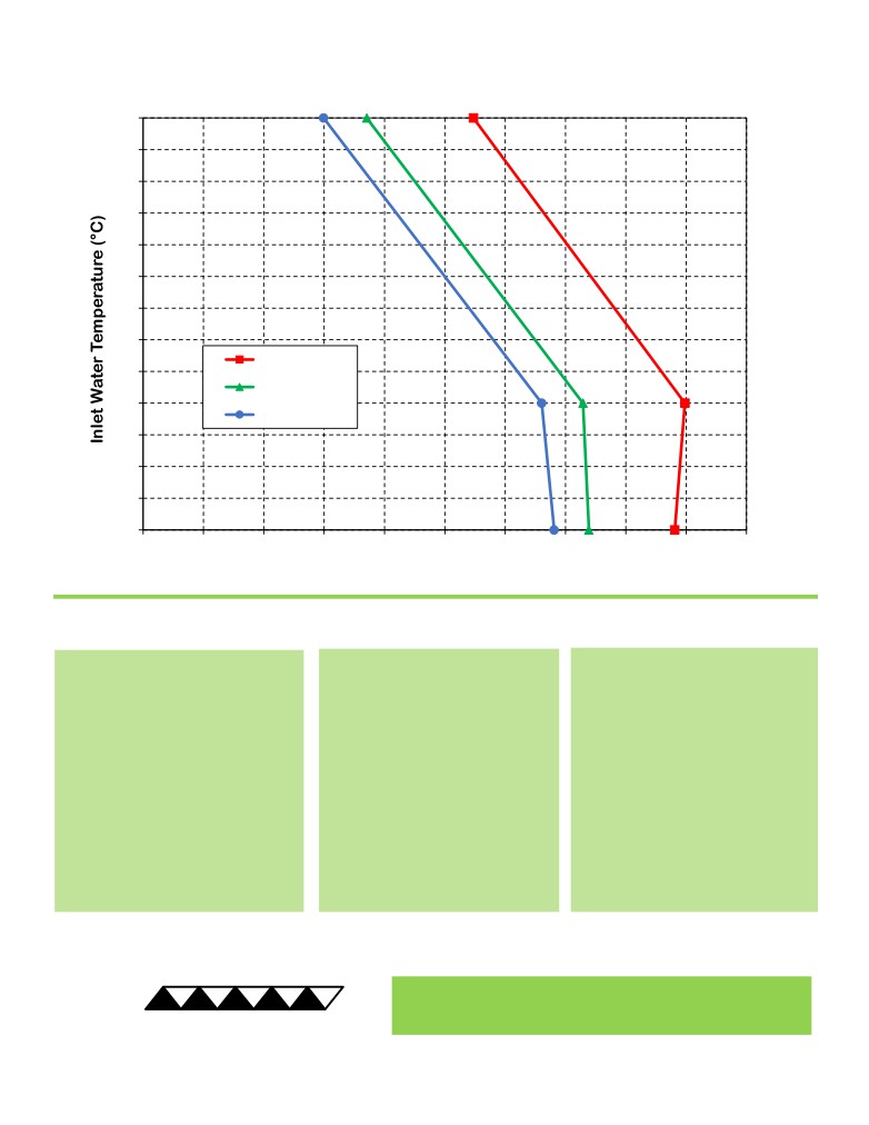
LC-061 Heating Performance Graph
(adding heat to water, flowing at 1.6 L/min)
70
65
60
55
50
45
40
35
25 °C ambient
30
0 °C ambient
25
-10 °C ambient
20
15
10
5
0
20
40
60
80
100
120
140
160
180
200
Heat Added to Water (watts)
How to use the Performance Graph:
1. Select Performance Line
2. Select Enclosure Temperature
3. Determine Heating Capacity
The diagonal lines represent heating
Draw a horizontal line on the graph
The maximum amount of heat that
performance at the indicated ambient
corresponding to the desired inlet
the cooler can add to the water is
air temperature (inlet temperature on
water temperature of the enclosure.
determined by the intersection point
the ambient-side fan). If the cooler is
Make the line intersect with the
(determined in previous step). If the
to operate at a different ambient,
performance line corresponding to
heat added to the water (including
then you must sketch in a new
the ambient temperature at which
heat generated by equipment inside)
performance line. This can be drawn
the cooler is to operate.
is greater than the enclosure’s heat
parallel to one of the existing lines,
loss, then the cooler will be able to
using the distance between the
heat to the desired temperature. A
existing lines as a scale to properly
higher capacity cooler will be
locate the new line.
needed if the total heat added is less
than the enclosure’s heat loss.
Example: You need to maintain the enclosure at 30 °C while in a -10 °C ambient. The cooler can add a maximum of
approximately 125 W of heat to the water. If the heat dissipation from the enclosure exceeds this (plus anything else
generating heat), you would need more coolers and/or a larger cooler.
® Expert Engineering, Precision Manufacturing:
Quality Thermal Solutions Delivered
TE
TECHNOLOGY, INC.
NOTE: All specifications are subject to change without notice.
© 2019 TE Technology, Inc.
LC-061 26-DEC-2019 Page 4 of 8
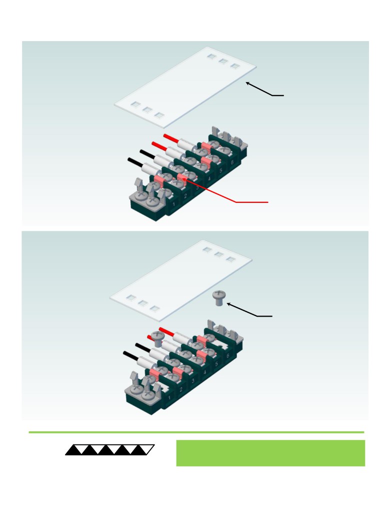
Terminal Block Configuration for Continuous Operation at Full Power
As-Shipped Configuration 1 of 2
1
REMOVE TERMINAL
BLOCK COVER
FOUR ELECTRICAL
JUMPERS INSTALLED
(ORIGINAL
CONFIGURATION)
2
LOOSEN TWO SCREWS
KEEP JUMPERS INSTALLED
® Expert Engineering, Precision Manufacturing:
Quality Thermal Solutions Delivered
TE
TECHNOLOGY, INC.
• cool@tetech.com • 231-929-3966 • 1590 Keane Drive • Traverse City, MI 49696
NOTE: All specifications are subject to change without notice.
© 2018 TE Technology, Inc.
LC-061 26-DEC-2019 Page 5 of 8
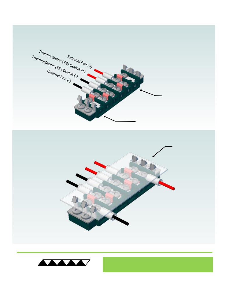
Terminal Block Configuration for Continuous Operation at Full Power
2 of 2
3
Power supply (+) Red Wire
to POSITION 6
Power supply (-) Black Wire
to POSITION 1
INSTALL WIRES,
4
TIGHTEN SCREWS
TO 1.0 N-M, AND
REPLACE COVER
® Expert Engineering, Precision Manufacturing:
Quality Thermal Solutions Delivered
TE
TECHNOLOGY, INC.
NOTE: All specifications are subject to change without notice.
© 2018 TE Technology, Inc.
LC-061 26-DEC-2019 Page 6 of 8
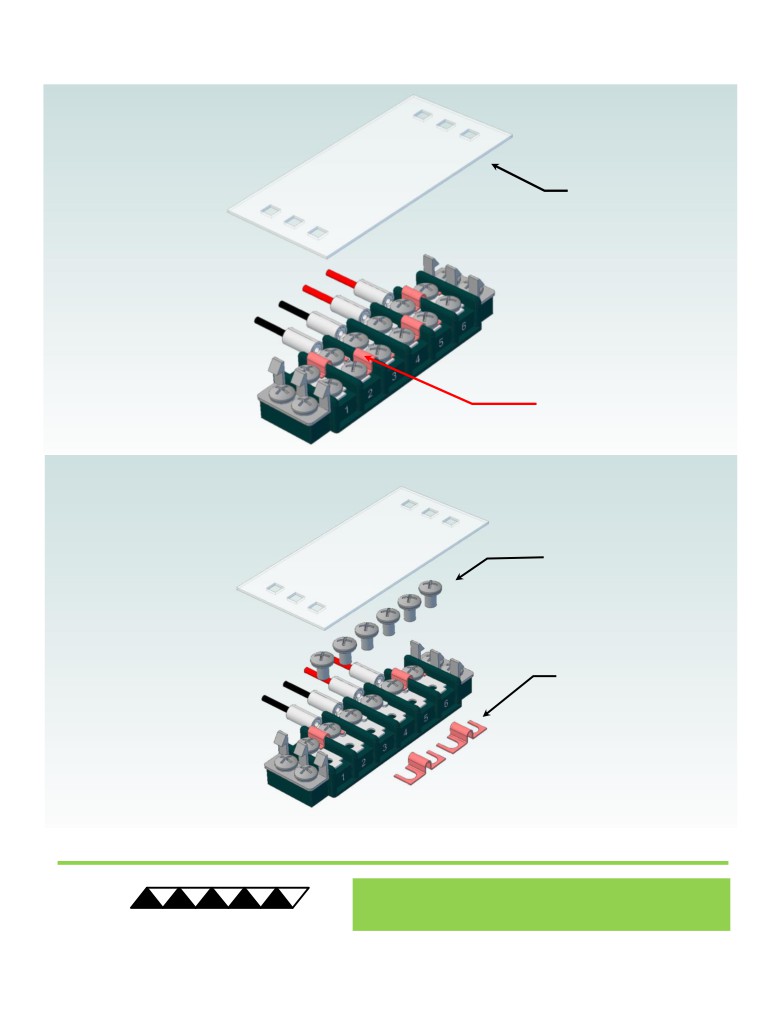
Terminal Block Configuration for Operation with Temperature Controller
1 of 2
1
REMOVE TERMINAL
BLOCK COVER
FOUR ELECTRICAL
JUMPERS INSTALLED
(ORIGINAL
CONFIGURATION)
2
LOOSEN SIX SCREWS
REMOVE TWO
ELECTRICAL JUMPERS
FROM 2-3 AND 4-5
® Expert Engineering, Precision Manufacturing:
Quality Thermal Solutions Delivered
TE
TECHNOLOGY, INC.
NOTE: All specifications are subject to change without notice.
© 2018 TE Technology, Inc.
LC-061 26-DEC-2019 Page 7 of 8
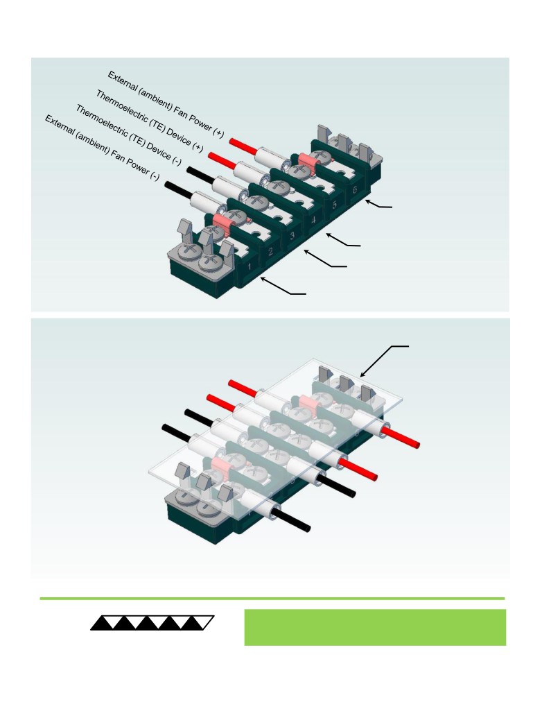
Terminal Block Configuration for Operation with Temperature Controller
2 of 2
3
Power supply (+) Red Wire
to POSITION 6
Temperature Controller (+) Red Wire
to POSITION 4
Temperature Controller (-) Black Wire
To POSITION 3
Power supply (-) Black Wire
to POSITION 1
INSTALL WIRES,
4
TIGHTEN SCREWS
TO 1.0 N-M, AND
REPLACE COVER
® Expert Engineering, Precision Manufacturing:
Quality Thermal Solutions Delivered
TE
TECHNOLOGY, INC.
NOTE: All specifications are subject to change without notice.
© 2018 TE Technology, Inc.
LC-061 26-DEC-2019 Page 8 of 8