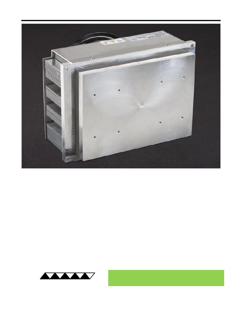
CP-200 Peltier-Thermoelectric Cold-Plate Cooler
• Heats as well as cools (when used with heat & cool / bipolar controller).
• Can be used to heat to 70°C; High Temperature (HT) version is available for heating to
100°C.
• Useful for large heat loads.
• Stainless steel liquid heat exchanger (LC-SSX1) can be attached for cooling corrosive
liquids.
• Provides effective direct-contact cooling which is ideal for precision temperature
control.
• Efficient bonded-fin heat sink keeps cooler small but effective.
• Threaded holes are located in the cold plate for easy attachment of a temperature
sensor, interface plates, and other cooled plates.
• High-temperature version and other customizations are available upon request.
• CE marked, RoHS compliant.
® Expert Engineering, Precision Manufacturing:
Quality Thermal Solutions Delivered
TE
TECHNOLOGY, INC.
NOTE: All specifications are subject to change without notice.
© 2018 TE Technology, Inc.
CP-200 5-FEB-2019 Page 1 of 8
Thermoelectric (TE) Power (typical)1,3 :
24 VDC at 14.1 A
NEMA Rating: NA
Thermoelectric (TE) Power (maximum)2,3 :
24 VDC at 17.8 A
CP-200
External (ambient) Fan Power:
24 VDC at 0.75 A
Specifications
Weight (kg):
6.3
External (ambient) Fan Noise:
55 dBA
Performance is based on unrestricted air flow to fans
and from air-flow outlets. Do not operate if the heat sink
or cold plate exceeds 70 °C. Do not operate fans at air
temperatures below -20 °C or over 70 °C.
information before purchasing or using this product.
1Current, at steady-state, is rated at +25 °C ambient, +25 °C internal, maximum heat removal. At -25 °C internal, the typical steady-state current is 13.6 A.
2Current, at steady-state operation under-worst case conditions, is rated at -20 °C ambient, +70 °C internal, maximum heat removal.
3 Total current consumption is sum of TE current and Fan current.
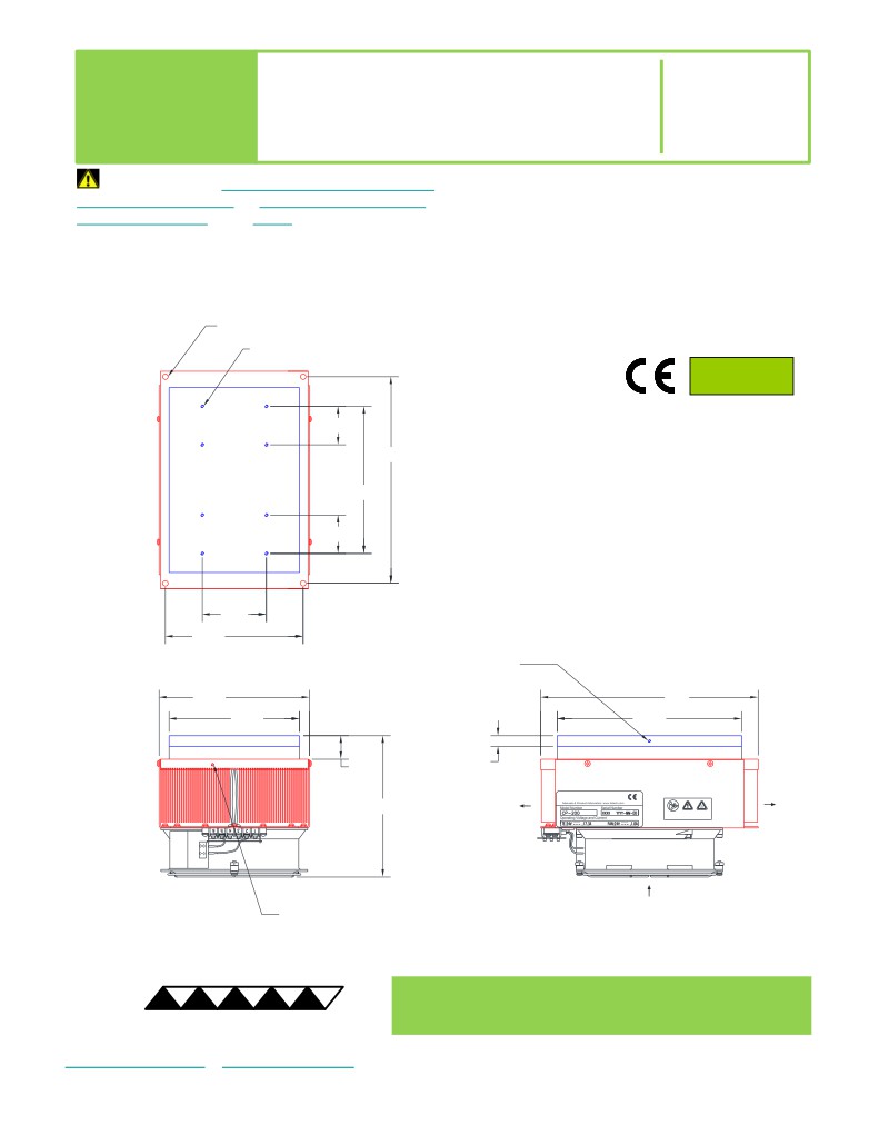
4X Ø6.4 THRU
8X M4 x 0.7 THREADING TAPPED 9.7 DEEP
RoHS Compliant
Directive 2011/65/EU
44.96
241.3
A 3D PDF, .stp, and .sldprt solid models
171.96
are also available from the website. Contact
TE Technology for 3D solid models in other
formats.
44.96
All dimensions in millimeters.
Cold plate shown in blue;
External (ambient) side shown in red.
74.93
161.04
25 DEEP HOLE with
M3 x 0.5 THREADING TAPPED 9.7 DEEP
for SENSOR MOUNTING
175.8
254
152.4
215.9
12.4
27.5
AMBIENT-SIDE
AMBIENT-SIDE
AIR FLOW OUTLET
AIR FLOW OUTLET
165.1
Download manual
AMBIENT-SIDE
AIR FLOW INLET
25 DEEP HOLE with
M3 x 0.5 THREADING TAPPED 9.7 DEEP
for SENSOR MOUNTING
® Expert Engineering, Precision Manufacturing:
Quality Thermal Solutions Delivered
TE
TECHNOLOGY, INC.
NOTE: All specifications are subject to change without notice.
© 2018 TE Technology, Inc.
CP-200 5-FEB-2019 Page 2 of 8
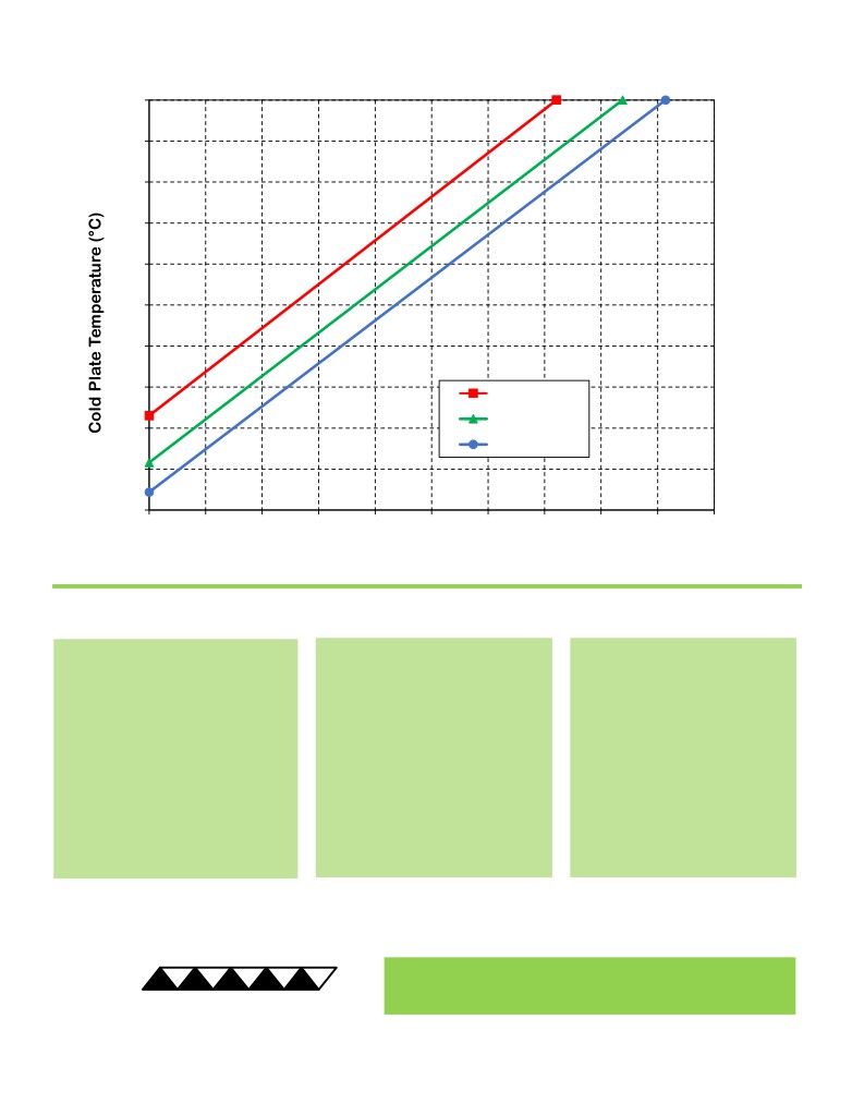
CP-200 Cooling Performance Graph
(removing heat from cold plate)
70
60
50
40
30
20
10
0
50 °C ambient
35 °C ambient
-10
25 °C ambient
-20
-30
0
40
80
120
160
200
240
280
320
360
400
Heat Removed from Cold Plate (watts)
How to use the Performance Graph:
1. Select Performance Line
2. Select Enclosure Temperature
3. Determine Cooling Capacity
The diagonal lines represent cooling
Draw a horizontal line on the graph
The maximum amount of heat
performance at the indicated ambient
corresponding to the desired cold-
that the cooler can remove from
air temperature (intake temperature
plate temperature. Make the line
the cold plate is determined by
on the ambient-side fan). If the cooler
intersect with the performance line
the intersection point (determined
is to operate at a different ambient,
corresponding to the ambient
in the previous step). The cooler
then you must sketch in a new
temperature at which the cooler is to
will be able to maintain the
performance line. This can be drawn
operate.
desired temperature if the cooling
parallel to one of the existing lines,
capacity exceeds the heat load. If
using the distance between the
the heat load exceeds the cooling
existing lines as a scale to properly
capacity then a higher capacity
locate the new line.
cooler will be needed.
Example: You need to maintain the cold plate at 10 °C while in a 25 °C ambient. The cooler can remove a maximum of
approximately 140 W of heat from the cold plate. If the heat gain from the ambient plus anything else actively
generating heat exceeds this, you would need a cooler with a larger cooling capacity or multiple coolers.
® Expert Engineering, Precision Manufacturing:
Quality Thermal Solutions Delivered
TE
TECHNOLOGY, INC.
NOTE: All specifications are subject to change without notice.
© 2018 TE Technology, Inc.
CP-200 5-FEB-2019 Page 3 of 8
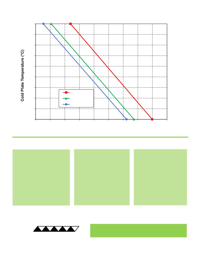
CP-200 Heating Performance Graph
(adding heat to cold plate)
70
60
50
40
30
20
10
25 °C ambient
0
0 °C ambient
-10 °C ambient
-10
-20
160
240
320
400
480
560
640
720
800
880
Heat Added to Cold Plate (watts)
How to use the Performance Graph:
1. Select Performance Line
2. Select Enclosure Temperature
3. Determine Heating Capacity
The diagonal lines represent heating
Draw a horizontal line on the graph
The maximum amount of heat
performance at the indicated ambient
corresponding to the desired cold-
that the cooler can add to the
air temperature (intake temperature
plate temperature. Make the line
cold plate is determined by the
on the ambient-side fan). If the cooler
intersect with the performance line
intersection point (determined in
is to operate at a different ambient,
corresponding to the ambient
the previous step). If the heat
then you must sketch in a new
temperature at which the cooler is
added to the cold plate (including
performance line. This can be drawn
to operate.
heat generated by equipment on
parallel to one of the existing lines,
the cold plate) is greater than the
using the distance between the
heat loss from the cold plate, then
existing lines as a scale to properly
the cooler will be able to heat to
locate the new line.
the desired temperature.
Example: You need to maintain the cold plate at 20 °C while in a 0 °C ambient. The cooler can add up to approximately
500 W of heat to the cold plate. If the heat dissipation from the cold plate to the ambient exceeds this (plus anything
else generating heat), you would need multiple coolers or a cooler with a larger heating capacity.
® Expert Engineering, Precision Manufacturing:
Quality Thermal Solutions Delivered
TE
TECHNOLOGY, INC.
NOTE: All specifications are subject to change without notice.
© 2018 TE Technology, Inc.
CP-200 5-FEB-2019 Page 4 of 8
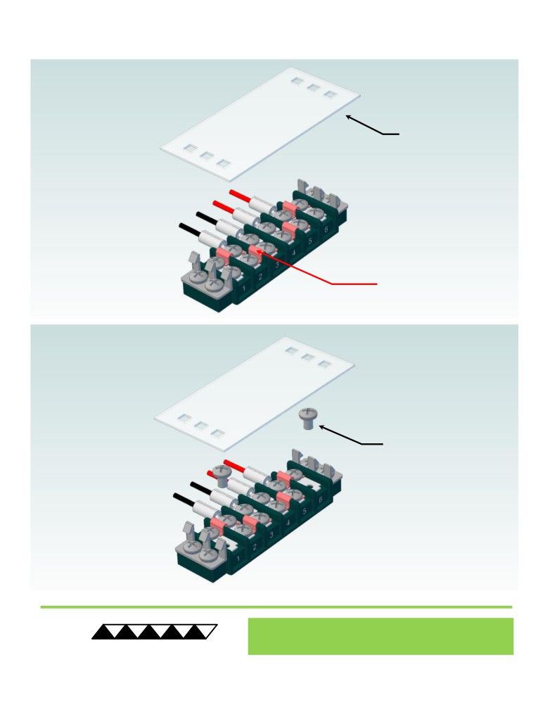
Terminal Block Configuration for Continuous Operation at Full Power
As-Shipped Configuration 1 of 2
1
REMOVE TERMINAL
BLOCK COVER
FOUR ELECTRICAL
JUMPERS INSTALLED
(ORIGINAL
CONFIGURATION)
2
LOOSEN TWO SCREWS
KEEP JUMPERS INSTALLED
® Expert Engineering, Precision Manufacturing:
Quality Thermal Solutions Delivered
TE
TECHNOLOGY, INC.
NOTE: All specifications are subject to change without notice.
© 2018 TE Technology, Inc.
CP-200 5-FEB-2019 Page 5 of 8
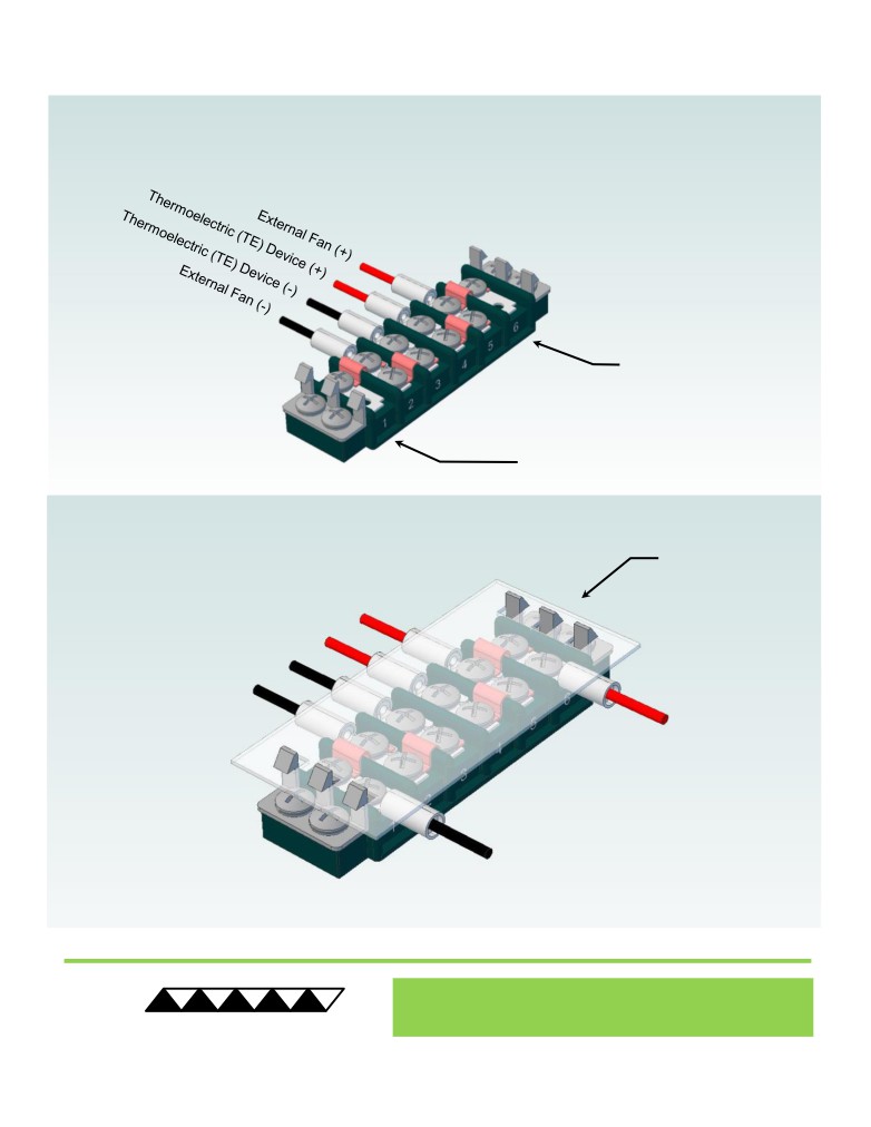
Terminal Block Configuration for Continuous Operation at Full Power
2 of 2
3
Power supply (+) Red Wire
to POSITION 6
Power supply (-) Black Wire
to POSITION 1
INSTALL WIRES,
4
TIGHTEN SCREWS
TO 1.0 N-M, AND
REPLACE COVER
® Expert Engineering, Precision Manufacturing:
Quality Thermal Solutions Delivered
TE
TECHNOLOGY, INC.
NOTE: All specifications are subject to change without notice.
© 2018 TE Technology, Inc.
CP-200 5-FEB-2019 Page 6 of 8
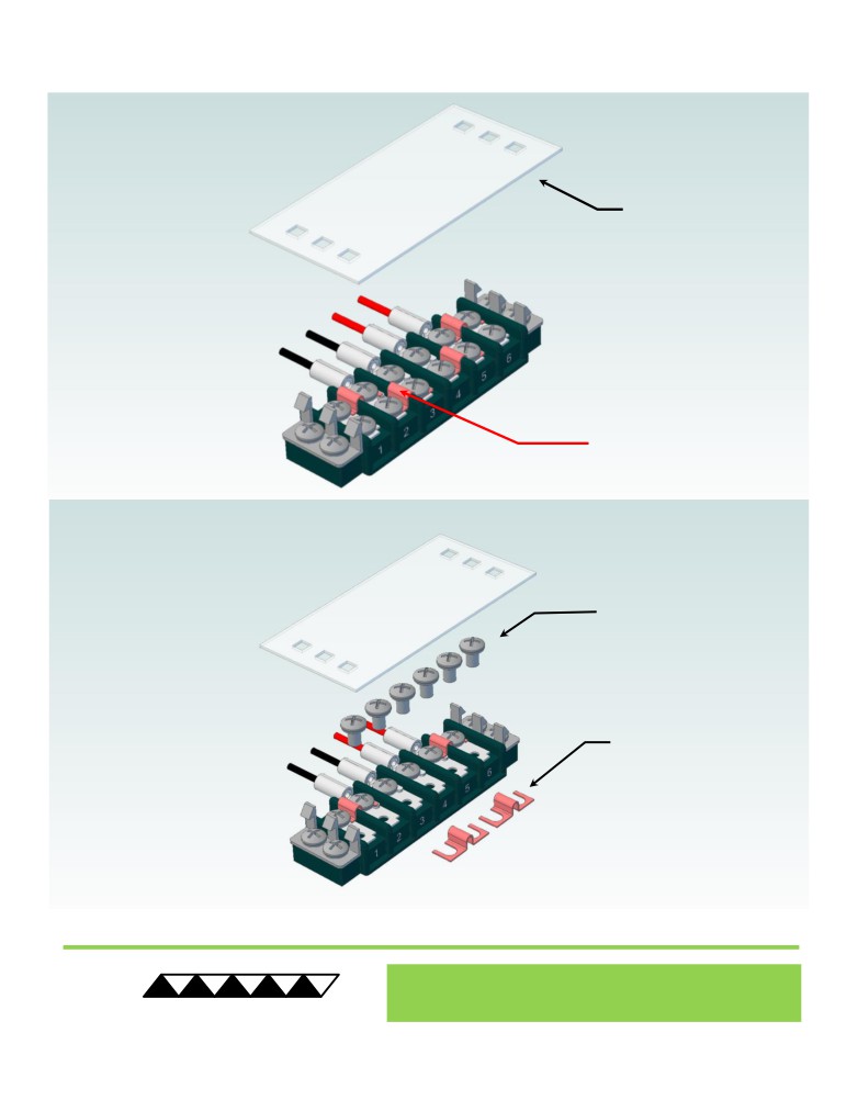
Terminal Block Configuration for Operation with Temperature Controller
1 of 2
1
REMOVE TERMINAL
BLOCK COVER
FOUR ELECTRICAL
JUMPERS INSTALLED
(ORIGINAL
CONFIGURATION)
2
LOOSEN SIX SCREWS
REMOVE TWO
ELECTRICAL JUMPERS
FROM 2-3 AND 4-5
® Expert Engineering, Precision Manufacturing:
Quality Thermal Solutions Delivered
TE
TECHNOLOGY, INC.
NOTE: All specifications are subject to change without notice.
© 2018 TE Technology, Inc.
CP-200 5-FEB-2019 Page 7 of 8
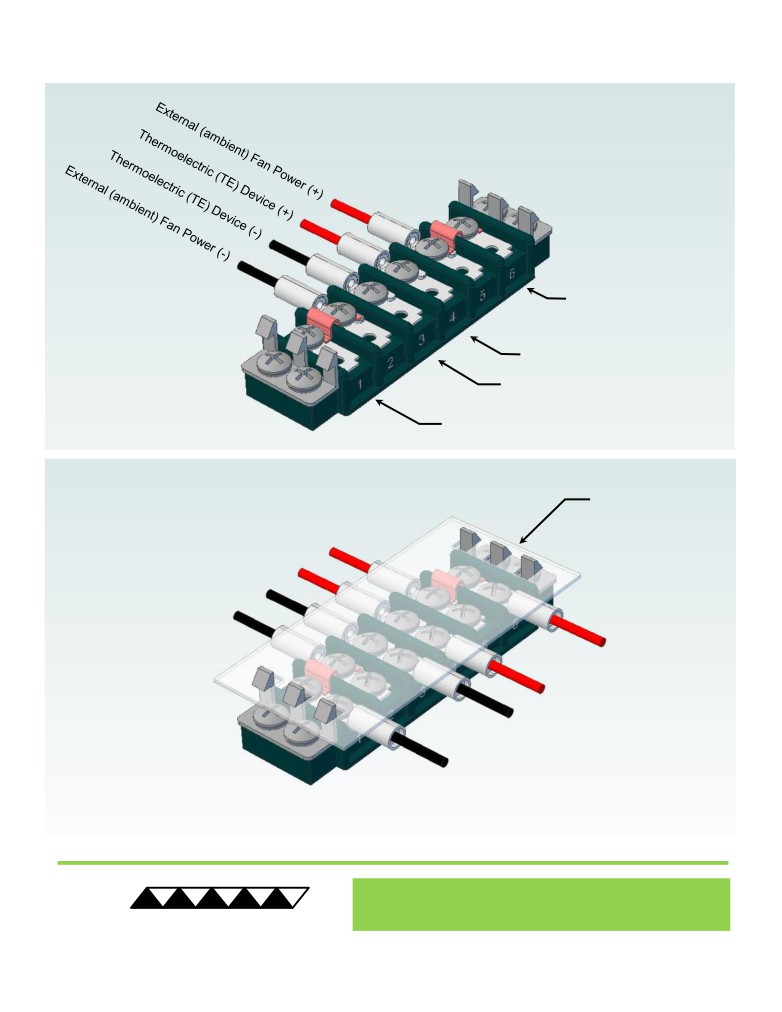
Terminal Block Configuration for Operation with Temperature Controller
2 of 2
3
Power supply (+) Red Wire
to POSITION 6
Temperature Controller (+) Red Wire
to POSITION 4
Temperature Controller (-) Black Wire
To POSITION 3
Power supply (-) Black Wire
to POSITION 1
INSTALL WIRES,
4
TIGHTEN SCREWS
TO 1.0 N-M, AND
REPLACE COVER
® Expert Engineering, Precision Manufacturing:
Quality Thermal Solutions Delivered
TE
TECHNOLOGY, INC.
NOTE: All specifications are subject to change without notice.
© 2018 TE Technology, Inc.
CP-200 5-FEB-2019 Page 8 of 8