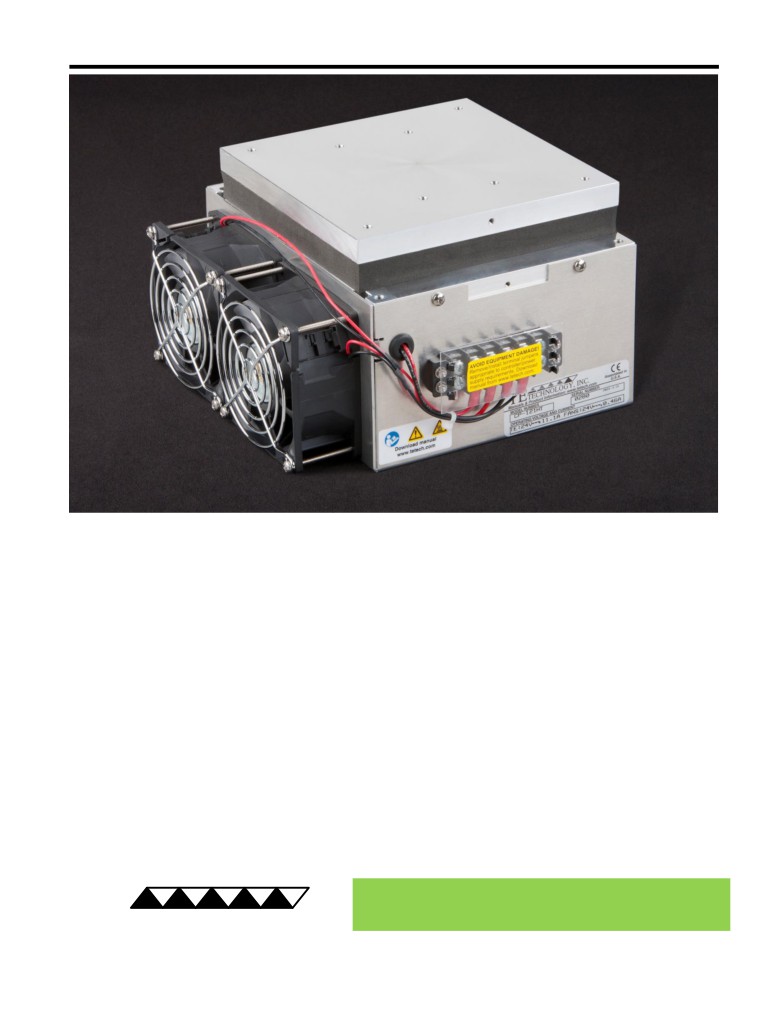
CP-121HT Peltier-Thermoelectric Cold-Plate Cooler
• Heats as well as cools (when used with heat & cool / bipolar controller).
• Can be used for heating to 100 °C.
• Ideal for medium to large heat loads, such as laser diodes, medical and laboratory
instruments, and thermal stabilization of electronic components.
• Provides effective direct-contact cooling which is ideal for precision temperature
control.
• Heat-sink air flows along the length of fins (in one end, out the opposite end).
• No additional modifications needed for bench-top use.
• Low fan noise (two fans, 39 dBA each) is beneficial in laboratory instrumentation.
• Threaded holes are located in cold plate for easy attachment of a temperature sensor,
interface plate, LC-SSX1 liquid exchanger, or other object.
• Customizations are available in production volumes for OEM users.
• CE marked, RoHS compliant.
® Expert Engineering, Precision Manufacturing:
Quality Thermal Solutions Delivered
TE
TECHNOLOGY, INC.
NOTE: All specifications are subject to change without notice.
© 2023 TE Technology, Inc.
CP-121HT 9-JAN-2023 Page 1 of 9
Thermoelectric (TE) Power (typical)1,3 :
24 VDC at 9.2 A
NEMA Rating: NA
Thermoelectric (TE) Power (maximum)2,3 :
24 VDC at 11.1 A
CP-121HT
External (ambient) Fan Power:
24 VDC at 0.30 A
Specifications
Weight (kg):
4.2
External (ambient) Fan Noise:
42 dBA
Performance is based on unrestricted air flow to fans
and from air-flow outlets. Do not operate if the heat sink
or cold plate exceeds 100 °C. Do not operate fans at air
temperatures below -10 °C or over 70 °C.
information before purchasing or using this product.
1Current, at steady-state, is rated at +25 °C ambient, +25 °C internal, maximum heat removal. At -23 °C internal, the typical steady-state current is 9.2 A.
2Current, at steady-state operation under-worst case conditions, is rated at -20 °C ambient, +70 °C internal, maximum heat removal.
3 Total current consumption is sum of TE current and Fan current.
139.7
RoHS Compliant
Directive 2011/65/EU
19.1
88.9
172.2
A 3D PDF, .stp, and .sldprt solid models
are also available from the website. Contact
TE Technology for 3D solid models in other
formats.
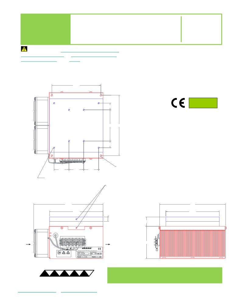
19.1
All dimensions in millimeters.
Cold plate shown in blue;
External (ambient) side shown in red.
4X M5 x 0.8 THREADING
42.5
41.9
42.5
TAPPED 9.7 DEEP
8X M4 x 0.7 THREADING
TAPPED 9.7 DEEP
25 DEEP HOLE with
M3 x 0.5 THREADING TAPPED 9.7 DEEP
for SENSOR MOUNTING
197.5
188
152.4
152.4
12.4
26.5
AMBIENT-SIDE
AMBIENT-SIDE
AIR FLOW INLET
AIR FLOW OUTLET
92.2
Download manual
® Expert Engineering, Precision Manufacturing:
Quality Thermal Solutions Delivered
TE
TECHNOLOGY, INC.
NOTE: All specifications are subject to change without notice.
© 2023 TE Technology, Inc.
CP-121HT 9-JAN-2023 Page 2 of 9
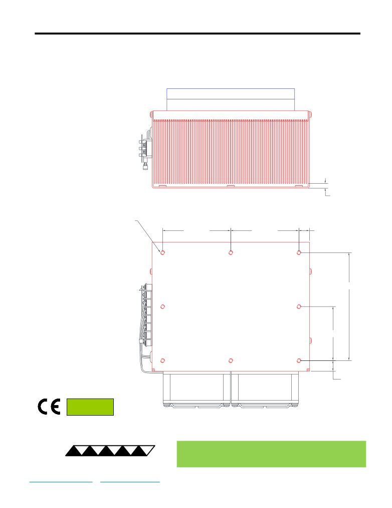
Bottom View of CP-121HT
Cooler can be mounted using the eight M5 x 0.8 PEM nuts located as shown in the base of the shroud
5.6
8X M5 X 0.8 THREADED PEM NUT
3X 81.28
3X 81.28
3X 12.7
3X 128.6
3X 64.31
3X 12.7
RoHS Compliant
Directive 2011/65/EU
® Expert Engineering, Precision Manufacturing:
Quality Thermal Solutions Delivered
TE
TECHNOLOGY, INC.
NOTE: All specifications are subject to change without notice.
© 2023 TE Technology, Inc.
CP-121HT 9-JAN-2023 Page 3 of 9
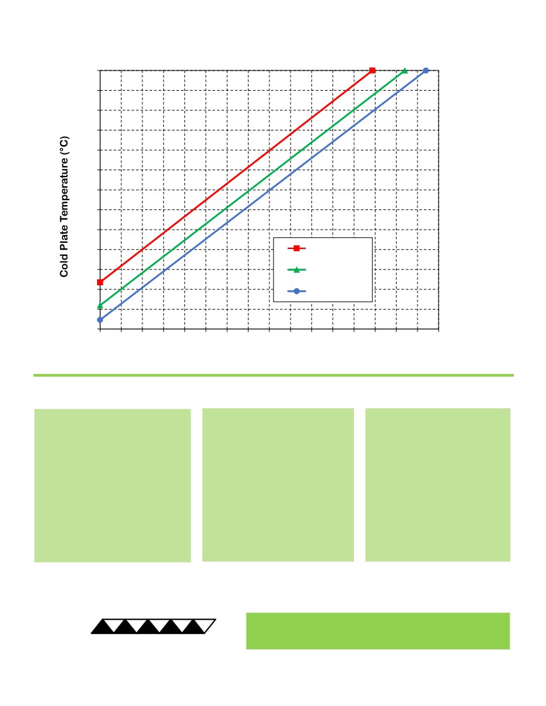
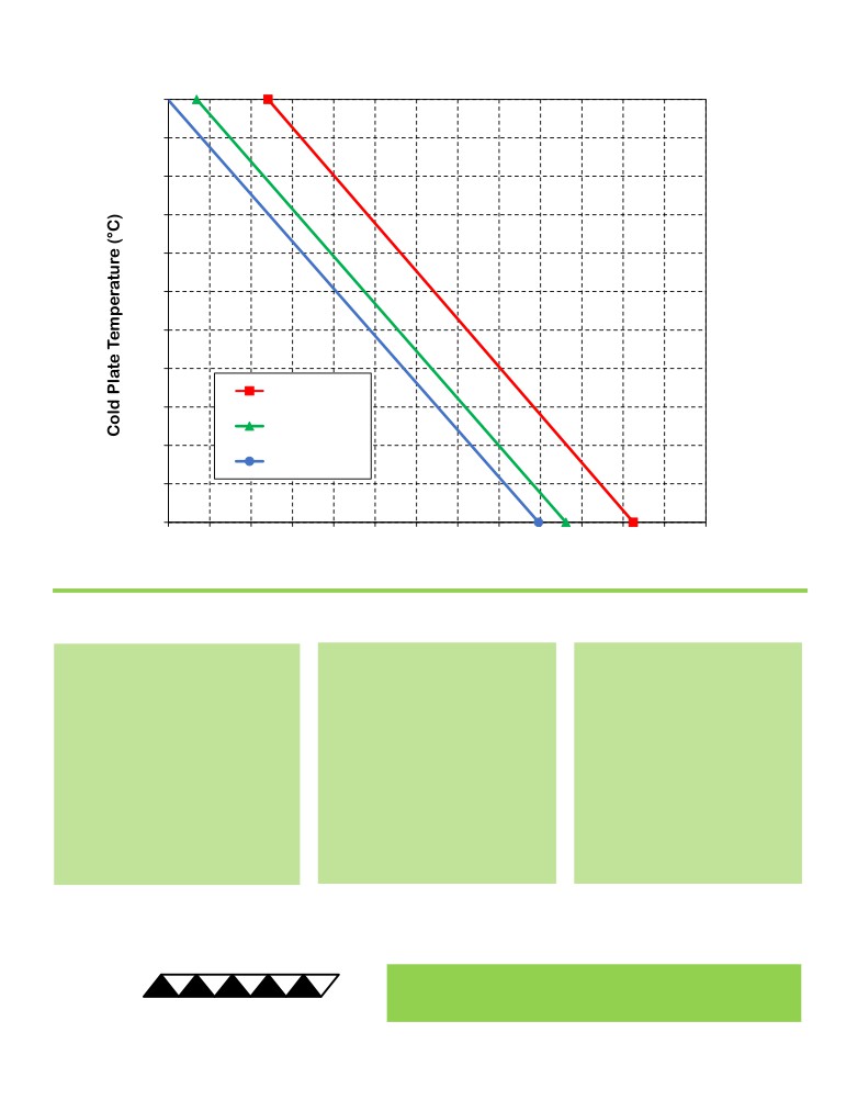
CP-121HT Cooling Performance Graph
(removing heat from cold plate)
100
90
80
70
60
50
40
30
20
10
50 °C ambient
0
35 °C ambient
-10
25 °C ambient
-20
-30
0
20
40
60
80
100
120
140
160
180
200
220
240
260
280
300
320
Heat Removed from Cold Plate (watts)
How to use the Performance Graph:
1. Select Performance Line
2. Select Enclosure Temperature
3. Determine Cooling Capacity
The diagonal lines represent cooling
Draw a horizontal line on the graph
The maximum amount of heat
performance at the indicated ambient
corresponding to the desired cold-
that the cooler can remove from
air temperature (intake temperature
plate temperature. Make the line
the cold plate is determined by
on the ambient-side fan). If the cooler
intersect with the performance line
the intersection point (determined
is to operate at a different ambient,
corresponding to the ambient
in the previous step). The cooler
then you must sketch in a new
temperature at which the cooler is to
will be able to maintain the
performance line. This can be drawn
operate.
desired temperature if the cooling
parallel to one of the existing lines,
capacity exceeds the heat load. If
using the distance between the
the heat load exceeds the cooling
existing lines as a scale to properly
capacity then a higher capacity
locate the new line.
cooler will be needed.
Example: You need to maintain the cold plate at 20 °C while in a 50 °C ambient. The cooler can remove a maximum of
approximately 65 W of heat from the cold plate. If the heat gain from the ambient plus anything else actively generating
heat exceeds this, you would need a cooler with a larger cooling capacity or multiple coolers.
® Expert Engineering, Precision Manufacturing:
Quality Thermal Solutions Delivered
TE
TECHNOLOGY, INC.
NOTE: All specifications are subject to change without notice.
© 2023 TE Technology, Inc.
CP-121HT 9-JAN-2023 Page 4 of 9
CP-121HT Heating Performance Graph
(adding heat to cold plate)
100
90
80
70
60
50
40
30
25 °C ambient
20
0 °C ambient
10
-10 °C ambient
0
-10
20
60
100
140
180
220
260
300
340
380
420
460
500
540
Heat Added to Cold Plate (watts)
How to use the Performance Graph:
1. Select Performance Line
2. Select Enclosure Temperature
3. Determine Heating Capacity
The diagonal lines represent heating
Draw a horizontal line on the graph
The maximum amount of heat
performance at the indicated ambient
corresponding to the desired cold-
that the cooler can add to the
air temperature (intake temperature
plate temperature. Make the line
cold plate is determined by the
on the ambient-side fan). If the cooler
intersect with the performance line
intersection point (determined in
is to operate at a different ambient,
corresponding to the ambient
the previous step). If the heat
then you must sketch in a new
temperature at which the cooler is
added to the cold plate (including
performance line. This can be drawn
to operate.
heat generated by equipment on
parallel to one of the existing lines,
the cold plate) is greater than the
using the distance between the
heat loss from the cold plate, then
existing lines as a scale to properly
the cooler will be able to heat to
locate the new line.
the desired temperature.
Example: You need to maintain the cold plate at 30 °C while in a 0 °C ambient. The cooler can add up to approximately
275 W of heat to the cold plate. If the heat dissipation from the cold plate to the ambient exceeds this (plus anything
else generating heat), you would need multiple coolers or a cooler with a larger heating capacity.
® Expert Engineering, Precision Manufacturing:
Quality Thermal Solutions Delivered
TE
TECHNOLOGY, INC.
NOTE: All specifications are subject to change without notice.
© 2023 TE Technology, Inc.
CP-121HT 9-JAN-2023 Page 5 of 9
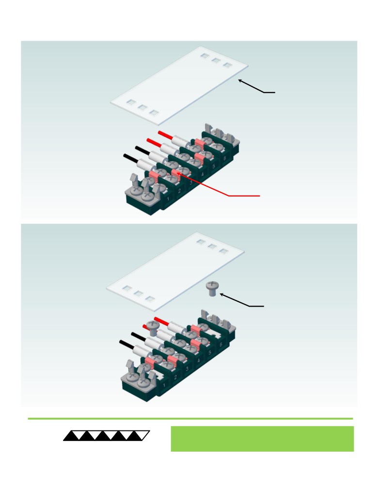
Terminal Block Configuration for Continuous Operation at Full Power
As-Shipped Configuration 1 of 2
1
REMOVE TERMINAL
BLOCK COVER
FOUR ELECTRICAL
JUMPERS INSTALLED
(ORIGINAL
CONFIGURATION)
2
LOOSEN TWO SCREWS
KEEP JUMPERS INSTALLED
® Expert Engineering, Precision Manufacturing:
Quality Thermal Solutions Delivered
TE
TECHNOLOGY, INC.
NOTE: All specifications are subject to change without notice.
© 2023 TE Technology, Inc.
CP-121HT 9-JAN-2023 Page 6 of 9
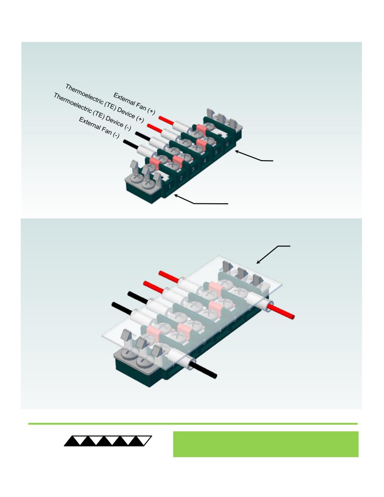
Terminal Block Configuration for Continuous Operation at Full Power
2 of 2
3
Power supply (+) Red Wire
to POSITION 6
Power supply (-) Black Wire
to POSITION 1
INSTALL WIRES,
4
TIGHTEN SCREWS
TO 1.0 N-M, AND
REPLACE COVER
® Expert Engineering, Precision Manufacturing:
Quality Thermal Solutions Delivered
TE
TECHNOLOGY, INC.
NOTE: All specifications are subject to change without notice.
© 2023 TE Technology, Inc.
CP-121HT 9-JAN-2023 Page 7 of 9
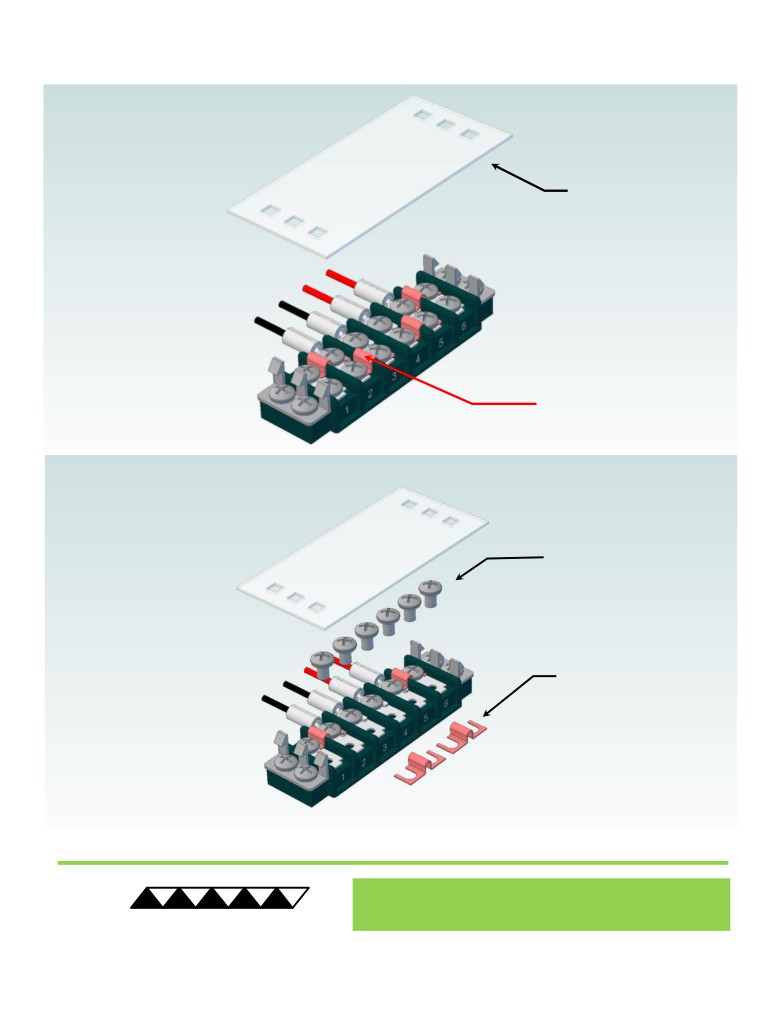
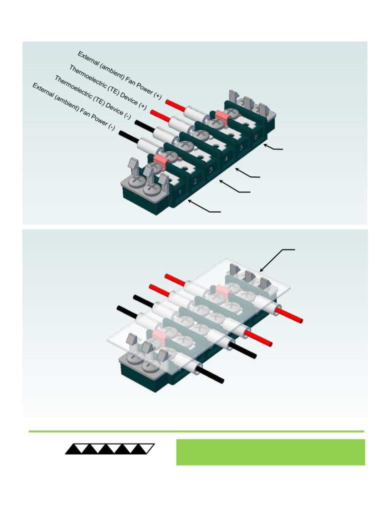
Terminal Block Configuration for Operation with Temperature Controller
1 of 2
1
REMOVE TERMINAL
BLOCK COVER
FOUR ELECTRICAL
JUMPERS INSTALLED
(ORIGINAL
CONFIGURATION)
2
LOOSEN SIX SCREWS
REMOVE TWO
ELECTRICAL JUMPERS
FROM 2-3 AND 4-5
® Expert Engineering, Precision Manufacturing:
Quality Thermal Solutions Delivered
TE
TECHNOLOGY, INC.
NOTE: All specifications are subject to change without notice.
© 2023 TE Technology, Inc.
CP-121HT 9-JAN-2023 Page 8 of 9
Terminal Block Configuration for Operation with Temperature Controller
2 of 2
3
Power supply (+) Red Wire
to POSITION 6
Temperature Controller (+) Red Wire
to POSITION 4
Temperature Controller (-) Black Wire
To POSITION 3
Power supply (-) Black Wire
to POSITION 1
INSTALL WIRES,
4
TIGHTEN SCREWS
TO 1.0 N-M, AND
REPLACE COVER
® Expert Engineering, Precision Manufacturing:
Quality Thermal Solutions Delivered
TE
TECHNOLOGY, INC.
NOTE: All specifications are subject to change without notice.
© 2023 TE Technology, Inc.
CP-121HT 9-JAN-2023 Page 9 of 9