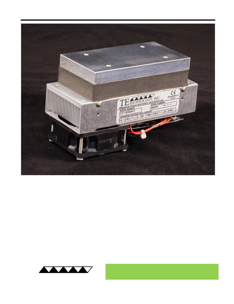
CP-040HT Peltier-Thermoelectric Cold-Plate Cooler
• Heats as well as cools (when used with heat & cool / bipolar controller).
• Provides effective, direct-contact cooling for small heat loads at low temperatures.
• Can also be used for heating up to 100 °C.
• Highly efficient 67 mm wide heat sink for compact size and low power consumption.
• Airflow can be blocked at one end of the heat sink, which provides more options for
routing air flow within instruments.
• Compatible with a wide range of temperature controllers.
• Threaded holes are located in the cold plate for easy attachment of a temperature
sensor, interface plates, and other cooled plates.
• An optional bracket is available for converting the cooler into a bench-top version.
• CE marked, RoHS compliant.
Expert Engineering, Precision Manufacturing:
Quality Thermal Solutions Delivered
NOTE: All specifications are subject to change without notice.
© 2024 TE Technology, Inc.
CP-040HT 09-OCT-2024 Page 1 of 10
Thermoelectric (TE) Power (typical)1,3 :
24 VDC at 2.7 A
NEMA Rating: NA
Thermoelectric (TE) Power (maximum)2,3 :
24 VDC at 3.4 A
CP-040HT
External (ambient) Fan Power:
24 VDC at 0.24 A
Specifications
Weight (kg):
0.74
External (ambient) Fan Noise:
46.5 dBA
Performance is based on unrestricted air flow to fans
and from air-flow outlets. Do not operate if the heat sink
or cold plate exceeds 100 °C. Do not operate fans at air
temperatures below -10 °C or over 70 °C.
information before purchasing or using this product.
1Current, at steady-state, is rated at +25 °C ambient, +25 °C internal, maximum heat removal. At -25 °C internal, the typical steady-state current is 2.6 A.
2Current, at steady-state operation under-worst case conditions, is rated at -10 °C ambient, +70 °C internal, maximum heat removal.
3 Total current consumption is sum of TE current and Fan current.
RoHS Compliant
Directive 2011/65/EU
A 3D PDF, .stp, and .sldprt solid models
are also available from the website. Contact
TE Technology for 3D solid models in other
formats.
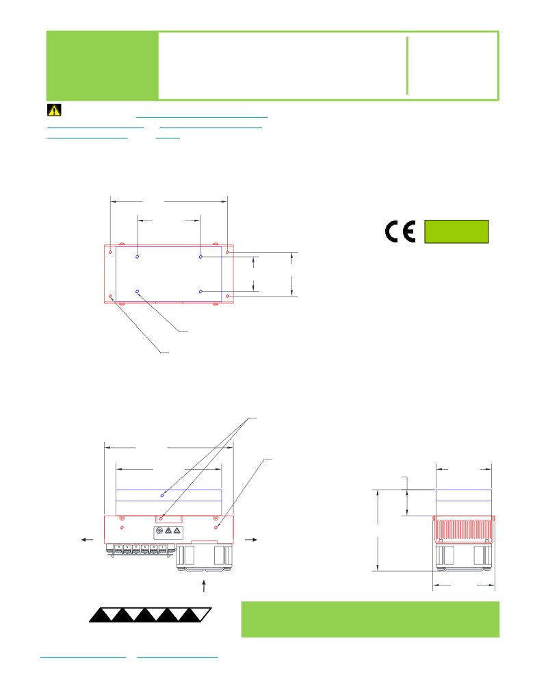
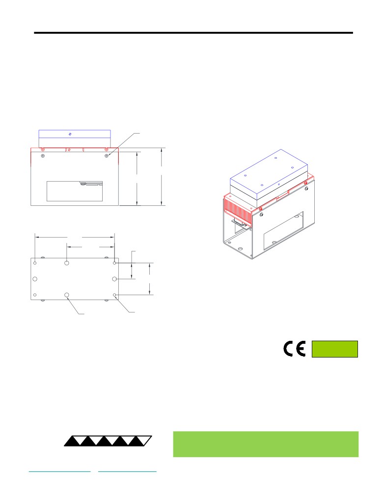
All dimensions in millimeters.
Cold plate shown in blue;
External (ambient) side shown in red.
Expert Engineering, Precision Manufacturing:
Quality Thermal Solutions Delivered
NOTE: All specifications are subject to change without notice.
© 2024 TE Technology, Inc.
CP-040HT 09-OCT-2024 Page 2 of 10
CP-040HT with Optional Mounting Bracket
(for converting to bench-top use)
RoHS Compliant
Directive 2011/65/EU
Expert Engineering, Precision Manufacturing:
Quality Thermal Solutions Delivered
NOTE: All specifications are subject to change without notice.
© 2024 TE Technology, Inc.
CP-040HT 09-OCT-2024 Page 3 of 10
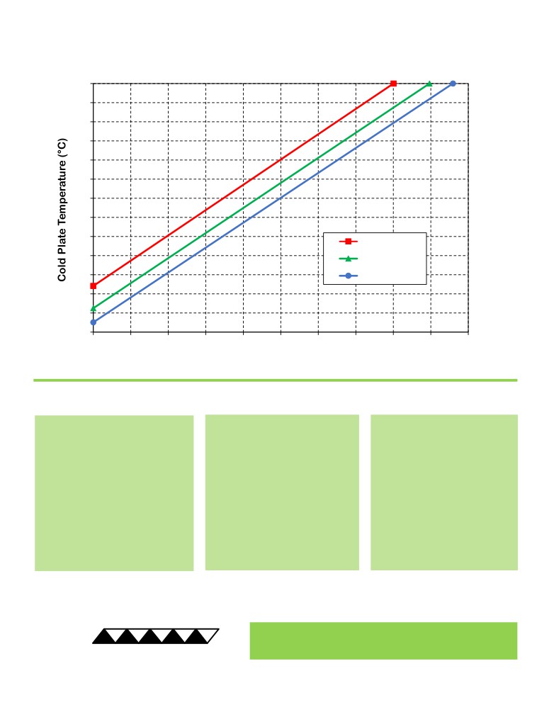
CP-040HT Cooling Performance Graph
(removing heat from cold plate)
How to use the Performance Graph:
1. Select Performance Line
2. Select Cold-plate Temperature
3. Determine Cooling Capacity
The diagonal lines represent cooling
Draw a horizontal line on the graph
The maximum amount of heat
performance at the indicated ambient
corresponding to the desired cold-
that the cooler can remove from
air temperature (intake temperature
plate temperature. Make the line
the cold plate is determined by
on the ambient-side fan). If the cooler
intersect with the performance line
the intersection point (determined
is to operate at a different ambient,
corresponding to the ambient
in the previous step). The cooler
then you must sketch in a new
temperature at which the cooler is to
will be able to maintain the
performance line. This can be drawn
operate.
desired temperature if the cooling
parallel to one of the existing lines,
capacity exceeds the heat load. If
using the distance between the
the heat load exceeds the cooling
existing lines as a scale to properly
capacity then a higher capacity
locate the new line.
cooler will be needed.
Example: You need to maintain the cold plate at 0 °C while in a 25 °C ambient. The cooler can remove a maximum of
approximately 20 W of heat from the cold plate. If the heat gain from the ambient plus anything else actively generating
heat exceeds this, you would need a cooler with a larger cooling capacity or multiple coolers.
Expert Engineering, Precision Manufacturing:
Quality Thermal Solutions Delivered
NOTE: All specifications are subject to change without notice.
© 2024 TE Technology, Inc.
CP-040HT 09-OCT-2024 Page 4 of 10
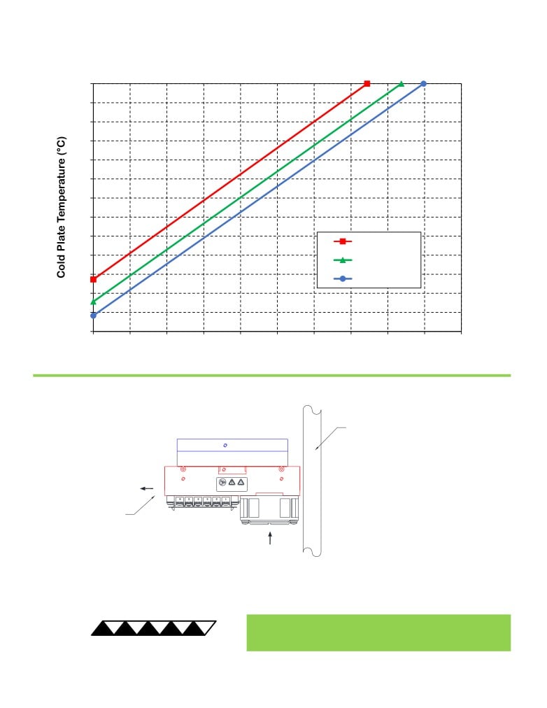
CP-040HT Cooling Performance Graph
with one end of the heat-sink blocked
(removing heat from cold plate)
The CP-040HT can be
installed with the exhaust
air obstructed on the fan
end of the heat sink with
only minimal impact to
performance.
NOTE: Do not obstruct the
opposite end of the heat sink.
Expert Engineering, Precision Manufacturing:
Quality Thermal Solutions Delivered
NOTE: All specifications are subject to change without notice.
© 2024 TE Technology, Inc.
CP-040HT 09-OCT-2024 Page 5 of 10
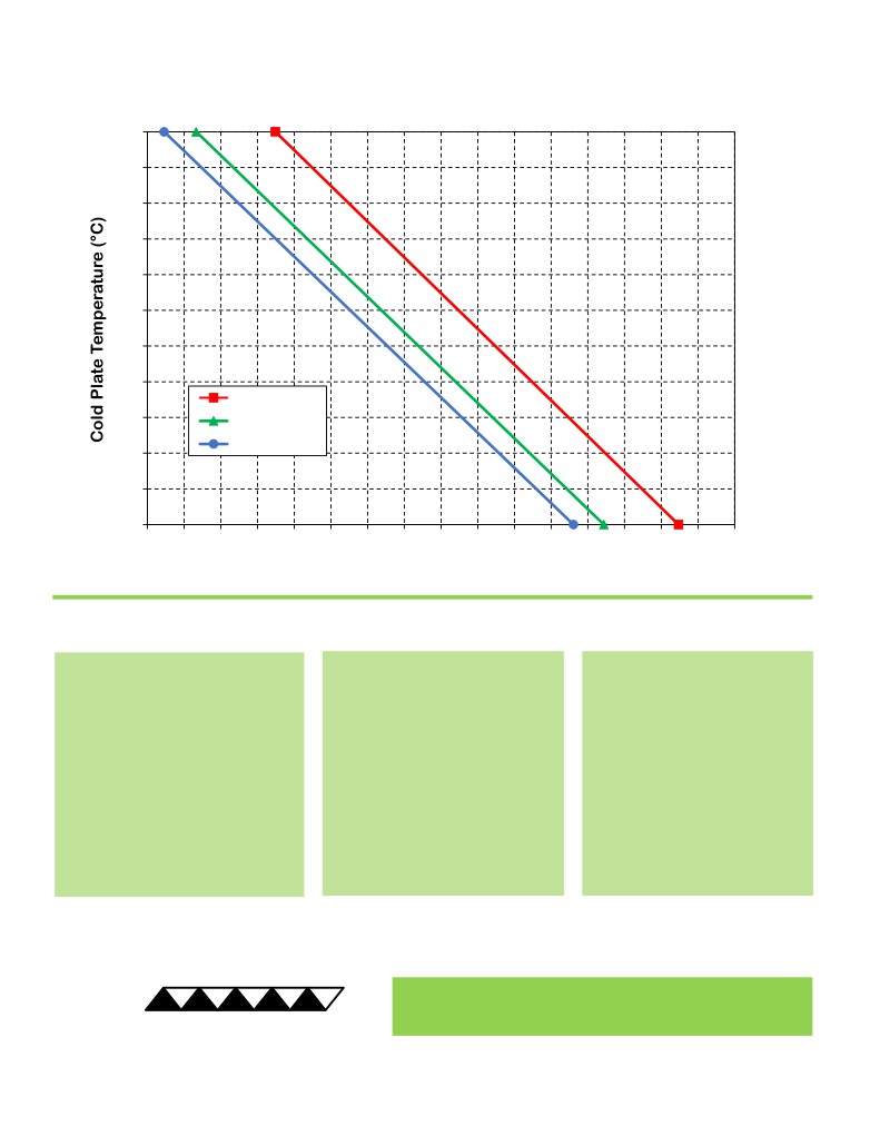
CP-040HT Heating Performance Graph
(adding heat to cold plate)
How to use the Performance Graph:
1. Select Performance Line
2. Select Cold-plate Temperature
3. Determine Heating Capacity
The diagonal lines represent heating
Draw a horizontal line on the graph
The maximum amount of heat
performance at the indicated ambient
corresponding to the desired cold-
that the cooler can add to the
air temperature (intake temperature
plate temperature. Make the line
cold plate is determined by the
on the ambient-side fan). If the cooler
intersect with the performance line
intersection point (determined in
is to operate at a different ambient,
corresponding to the ambient
the previous step). If the heat
then you must sketch in a new
temperature at which the cooler is
added to the cold plate (including
performance line. This can be drawn
to operate.
heat generated by equipment on
parallel to one of the existing lines,
the cold plate) is greater than the
using the distance between the
heat loss from the cold plate, then
existing lines as a scale to properly
the cooler will be able to heat to
locate the new line.
the desired temperature.
Example: You need to maintain the cold plate at 30 °C while in a 25 °C ambient. The cooler can add up to
approximately 105 W of heat to the cold plate. If the heat dissipation from the cold plate to the ambient exceeds this
(plus anything else generating heat), you would need multiple coolers or a cooler with a larger heating capacity.
Expert Engineering, Precision Manufacturing:
Quality Thermal Solutions Delivered
NOTE: All specifications are subject to change without notice.
© 2024 TE Technology, Inc.
CP-040HT 09-OCT-2024 Page 6 of 10
Terminal Block Configuration for Continuous Operation at Full Power
As-Shipped Configuration 1 of 2
1
2
Expert Engineering, Precision Manufacturing:
Quality Thermal Solutions Delivered
NOTE: All specifications are subject to change without notice.
© 2024 TE Technology, Inc.
CP-040HT 09-OCT-2024 Page 7 of 10
Terminal Block Configuration for Continuous Operation at Full Power
2 of 2
3
Expert Engineering, Precision Manufacturing:
Quality Thermal Solutions Delivered
NOTE: All specifications are subject to change without notice.
© 2024 TE Technology, Inc.
CP-040HT 09-OCT-2024 Page 8 of 10
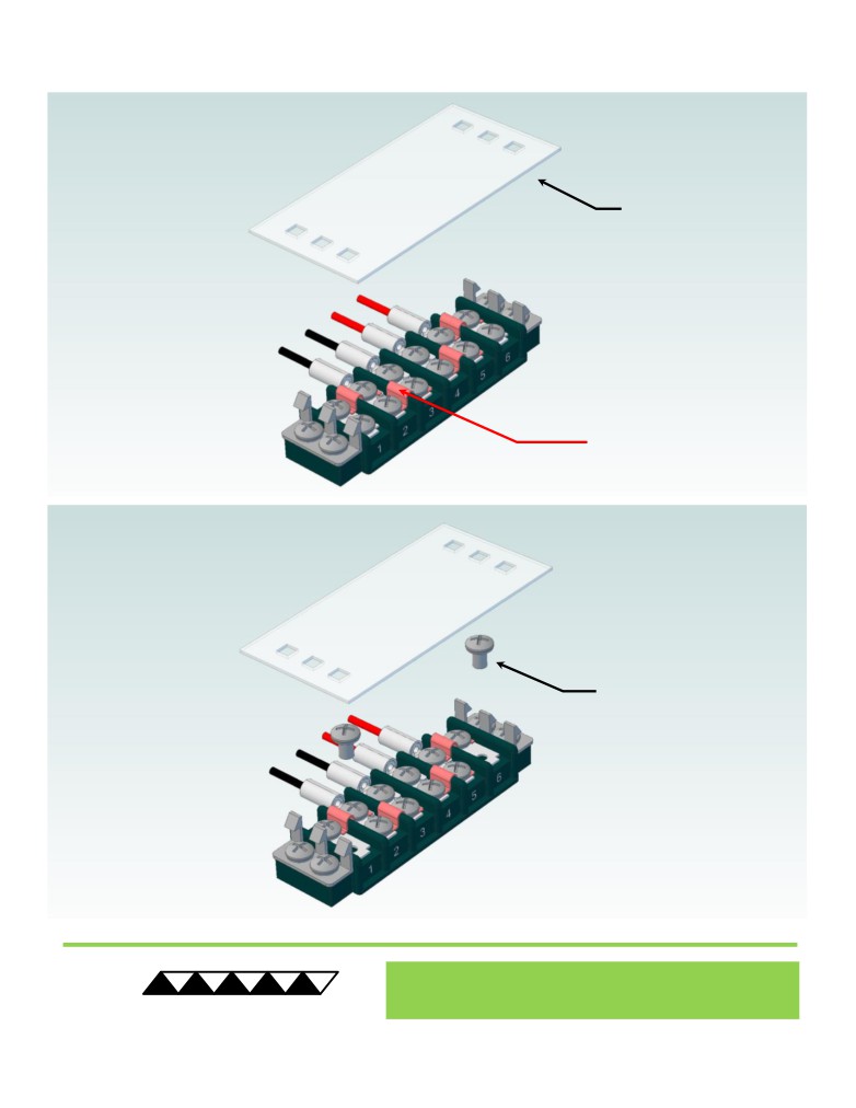
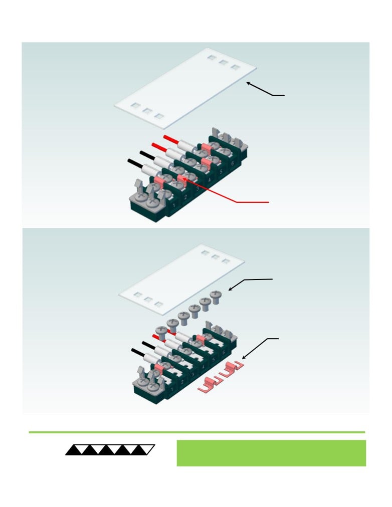
Terminal Block Configuration for Operation with Temperature Controller
1 of 2
1
2
Expert Engineering, Precision Manufacturing:
Quality Thermal Solutions Delivered
NOTE: All specifications are subject to change without notice.
© 2024 TE Technology, Inc.
CP-040HT 09-OCT-2024 Page 9 of 10
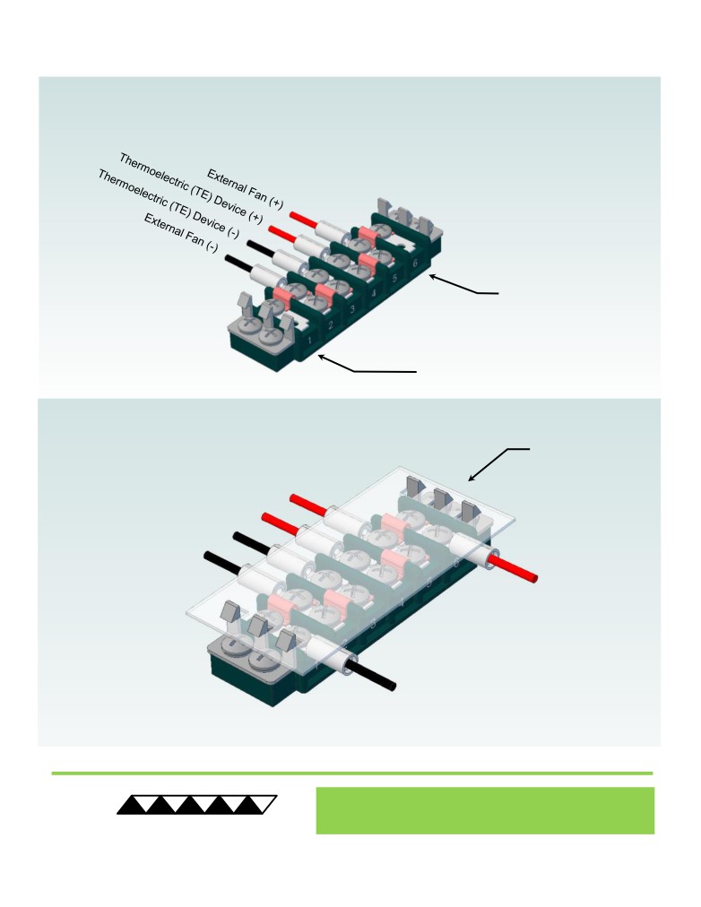
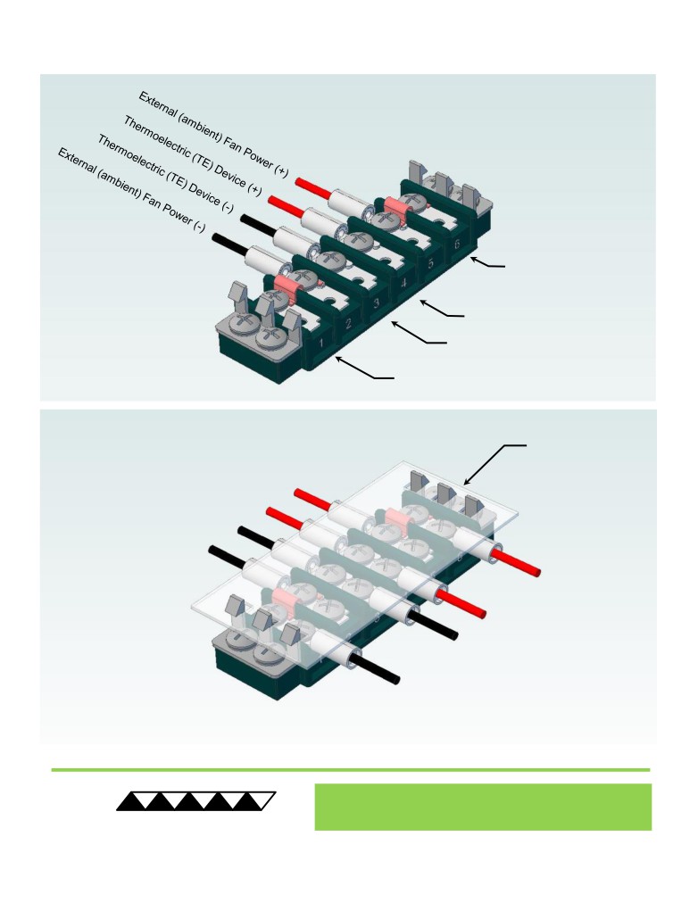
Terminal Block Configuration for Operation with Temperature Controller
2 of 2
3
4
Expert Engineering, Precision Manufacturing:
Quality Thermal Solutions Delivered
NOTE: All specifications are subject to change without notice.
© 2024 TE Technology, Inc.
CP-040HT 09-OCT-2024 Page 10 of 10