CP-035HT Peltier-Thermoelectric Cold-Plate Cooler
• TE Technology's smallest cold plate cooler.
• Low thermal mass reduces cool-down times.
• Heats as well as cools (when used with heat & cool/bipolar controller).
• Can be used for heating up to 100 °C.
• Compatible with all of TE Technology's controllers.
• An optional mounting bracket is available for converting the cooler into a
bench-top version.
• Threaded holes located in the cold plate for attachment of a temperature
sensor, interface plate, or object to be cooled.
• Mounting holes located in face of heat sink and sides of shroud for extra
mounting options.
Expert Engineering, Precision Manufacturing:
Quality Thermal Solutions Delivered
NOTE: All specifications are subject to change without notice.
© 2023 TE Technology, Inc.
CP-035HT 10-JUN-2024 Page 1 of 10
Thermoelectric (TE) Power (typical)1,3 :
12 VDC at 4.3 A
NEMA Rating: NA
Thermoelectric (TE) Power (maximum)2,3 :
12 VDC at 5.3 A
CP-035HT
External (ambient) Fan Power:
12 VDC at 0.26 A
Specifications
Weight (kg):
0.39
External (ambient) Fan Noise:
43 dBA
Performance is based on unrestricted air flow to fans
and from air-flow outlets. Do not operate if the heat sink
or cold plate exceeds 100 °C. Do not operate fans at air
temperatures below -10 °C or over 70 °C.
information before purchasing or using this product.
1Current, at steady-state, is rated at +25 °C ambient, +25 °C internal, maximum heat removal. At -19 °C internal, the typical steady-state current is 4.1 A.
2Current, at steady-state operation under-worst case conditions, is rated at -10 °C ambient, +70 °C internal, maximum heat removal.
3 Total current consumption is sum of TE current and Fan current.
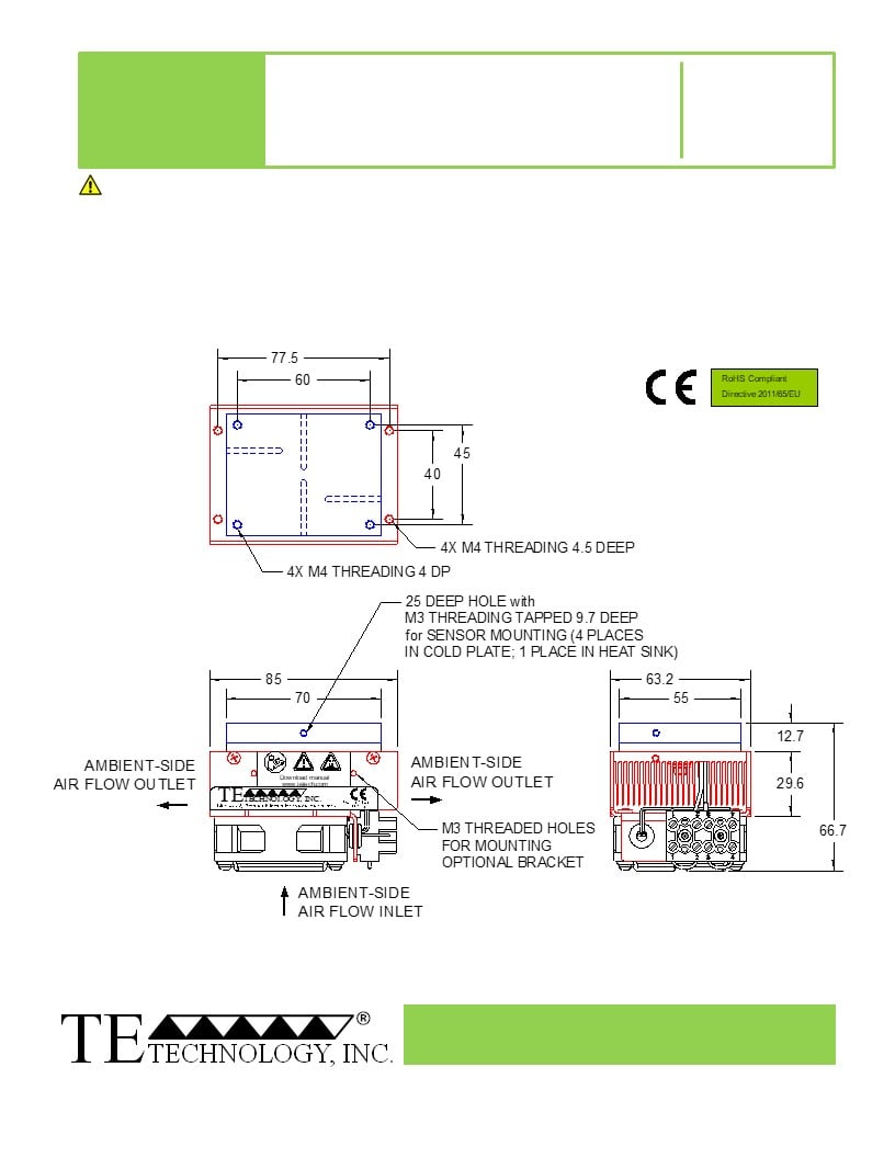
A 3D PDF, .stp, and .x_t solid models
are also available from the website. Contact
TE Technology for 3D solid models in other
formats.
All dimensions in millimeters.
Cold plate shown in blue;
External (ambient) side shown in red.
Expert Engineering, Precision Manufacturing:
Quality Thermal Solutions Delivered
NOTE: All specifications are subject to change without notice.
© 2023 TE Technology, Inc.
CP-035HT 10-JUN-2024 Page 2 of 10
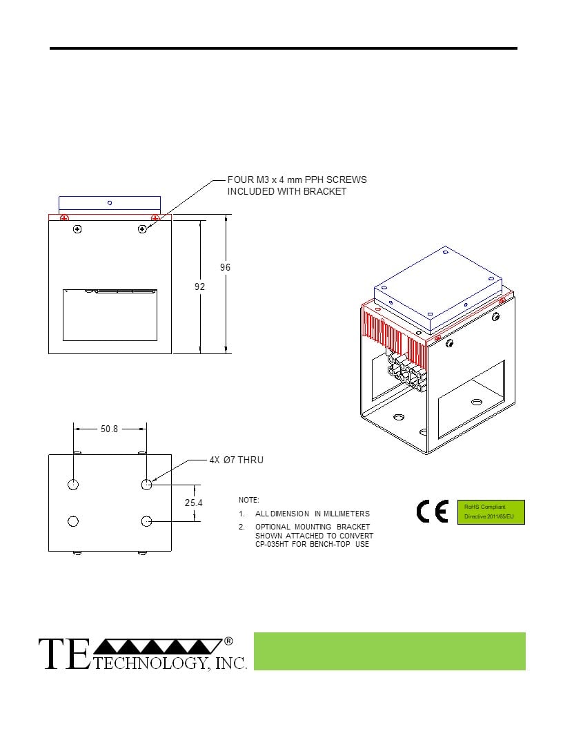
CP-035HT with Optional Mounting Bracket
(for converting to bench-top use)
Expert Engineering, Precision Manufacturing:
Quality Thermal Solutions Delivered
NOTE: All specifications are subject to change without notice.
© 2023 TE Technology, Inc.
CP-035HT 10-JUN-2024 Page 3 of 10
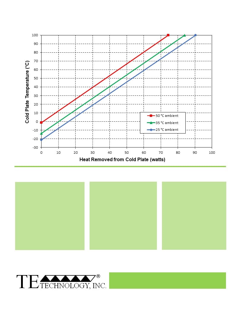
CP-035HT Cooling Performance Graph
(removing heat from cold plate)
How to use the Performance Graph:
1. Select Performance Line
2. Select Enclosure Temperature
3. Determine Cooling Capacity
The diagonal lines represent cooling
Draw a horizontal line on the graph
The maximum amount of heat
performance at the indicated ambient
corresponding to the desired cold-
that the cooler can remove from
air temperature (intake temperature
plate temperature. Make the line
the cold plate is determined by
on the ambient-side fan). If the cooler
intersect with the performance line
the intersection point (determined
is to operate at a different ambient,
corresponding to the ambient
in the previous step). The cooler
then you must sketch in a new
temperature at which the cooler is to
will be able to maintain the
performance line. This can be drawn
operate.
desired temperature if the cooling
parallel to one of the existing lines,
capacity exceeds the heat load. If
using the distance between the
the heat load exceeds the cooling
existing lines as a scale to properly
capacity then a higher capacity
locate the new line.
cooler will be needed.
Example: You need to maintain the cold plate at 0 °C while in a 25 °C ambient. The cooler can remove a maximum of
approximately 16 W of heat from the cold plate. If the heat gain from the ambient plus anything else actively generating
heat exceeds this, you would need a cooler with a larger cooling capacity or multiple coolers.
Expert Engineering, Precision Manufacturing:
Quality Thermal Solutions Delivered
NOTE: All specifications are subject to change without notice.
© 2023 TE Technology, Inc.
CP-035HT 10-JUN-2024 Page 4 of 10
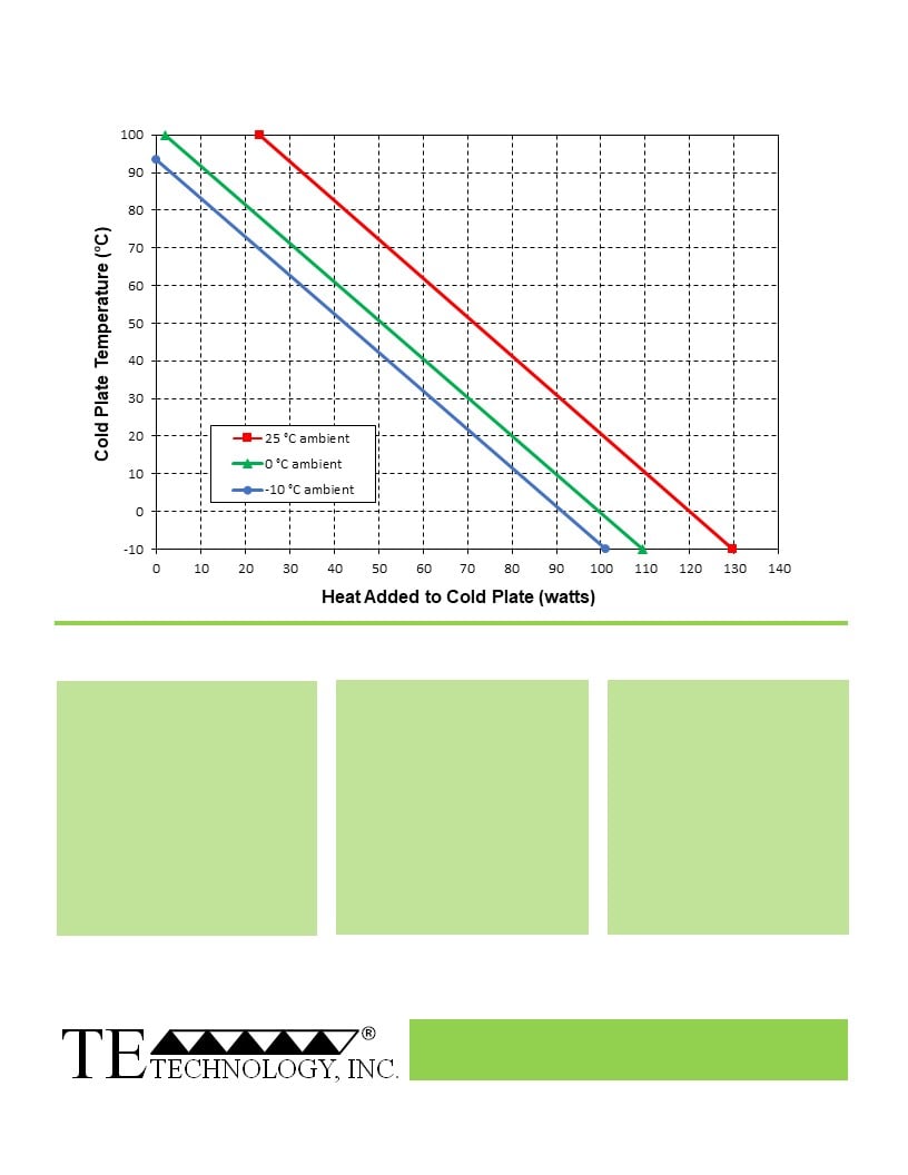
CP-035HT Heating Performance Graph
(adding heat to cold plate)
How to use the Performance Graph:
1. Select Performance Line
2. Select Enclosure Temperature
3. Determine Heating Capacity
The diagonal lines represent heating
Draw a horizontal line on the graph
The maximum amount of heat
performance at the indicated ambient
corresponding to the desired cold-
that the cooler can add to the
air temperature (intake temperature
plate temperature. Make the line
cold plate is determined by the
on the ambient-side fan). If the cooler
intersect with the performance line
intersection point (determined in
is to operate at a different ambient,
corresponding to the ambient
the previous step). If the heat
then you must sketch in a new
temperature at which the cooler is
added to the cold plate (including
performance line. This can be drawn
to operate.
heat generated by equipment on
parallel to one of the existing lines,
the cold plate) is greater than the
using the distance between the
heat loss from the cold plate, then
existing lines as a scale to properly
the cooler will be able to heat to
locate the new line.
the desired temperature.
Example: You need to maintain the cold plate at 30 °C while in a 25 °C ambient. The cooler can add up to
approximately 91 W of heat to the cold plate. If the heat dissipation from the cold plate to the ambient exceeds this
(plus anything else generating heat), you would need multiple coolers or a cooler with a larger heating capacity.
Expert Engineering, Precision Manufacturing:
Quality Thermal Solutions Delivered
NOTE: All specifications are subject to change without notice.
© 2023 TE Technology, Inc.
CP-035HT 10-JUN-2024 Page 5 of 10
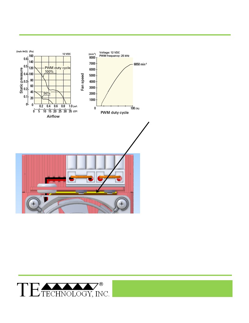
CP-035HT Fan Speed Connections
The fan speed operates at 100% as
shipped. DO NOT OPERATE THE CP-
035HT IN COOOLING MODE WITH A PWM
DUTY CYCLE OF LESS THAN 50%. DO
NOT ALLOW THE HEAT SINK OR COLD
PLATE TEMPERATURES TO EXCEED
100 °C.
The fan speed can be controlled using
pulse-width modulation at a recommneded
5 kHz to 25 kHz frequency range, applied
to the brown fan wire. The TC-720
temperature controller can be used to
provide this PWM signal to reduce the
audible noise at low cooling demands (use
5400 Hz frequency setting).
The yellow wire provides fan-speed
sensing. Consult with TE Technology if
you wish to use this feature.
Brown Wire: Speed Control
Yellow Wire: Speed Sensor
The brown and yellow wires are usually not
used and are therefore wrapped in heat
shrink.
If using these features, carefully cut away the
heat shrink. Additional wire length can be
splice on as needed.
Expert Engineering, Precision Manufacturing:
Quality Thermal Solutions Delivered
NOTE: All specifications are subject to change without notice.
© 2023 TE Technology, Inc.
CP-035HT 10-JUN-2024 Page 6 of 10
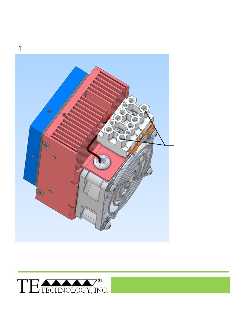
Terminal Block Configuration for Continuous Operation at Full Power
As-Shipped Configuration 1 of 2
LOOSEN TWO SCREWS
KEEP JUMPERS INSTALLED
Expert Engineering, Precision Manufacturing:
Quality Thermal Solutions Delivered
NOTE: All specifications are subject to change without notice.
© 2023 TE Technology, Inc.
CP-035HT 10-JUN-2024 Page 7 of 10
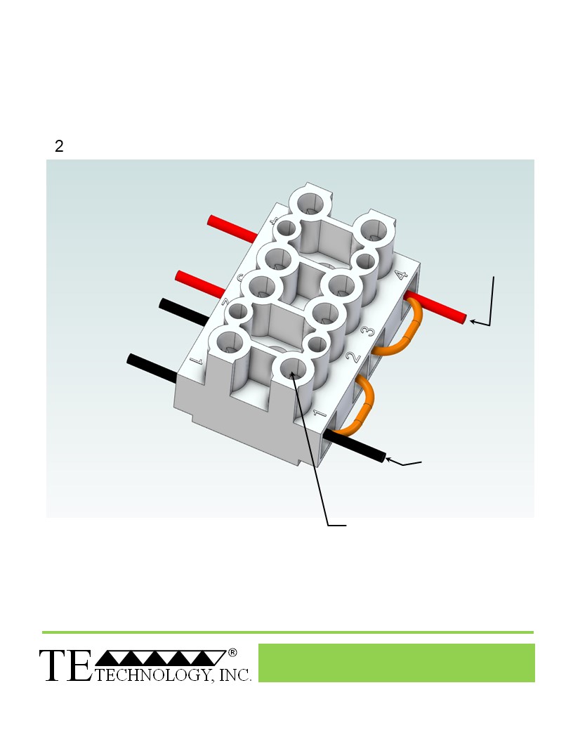
Terminal Block Configuration for Continuous Operation at Full Power
2 of 2
Power supply (+) Red Wire
to POSITION 4
Power supply (-) Black Wire
to POSITION 1
INSTALL WIRES,
TIGHTEN SCREWS
to 0.6 N·m
External Fan (+)
Thermoelectric (TE) Device (+)
Thermoelectric (TE) Device (-)
External Fan (-)
Expert Engineering, Precision Manufacturing:
Quality Thermal Solutions Delivered
NOTE: All specifications are subject to change without notice.
© 2023 TE Technology, Inc.
CP-035HT 10-JUN-2024 Page 8 of 10
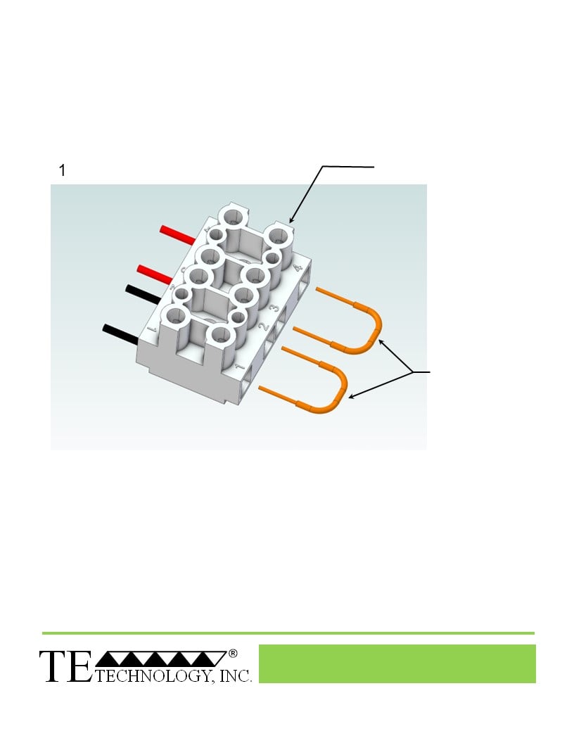
Terminal Block Configuration for Operation with Temperature Controller
1 of 2
LOOSEN 4 SCREWS
REMOVE TWO
ELECTRICAL JUMPERS
FROM 1-2 AND 3-4
Expert Engineering, Precision Manufacturing:
Quality Thermal Solutions Delivered
NOTE: All specifications are subject to change without notice.
© 2023 TE Technology, Inc.
CP-035HT 10-JUN-2024 Page 9 of 10
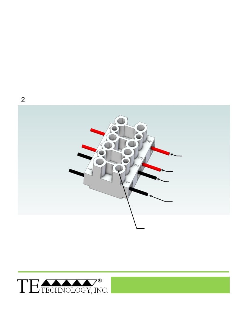
Terminal Block Configuration for Operation with Temperature Controller
2 of 2
Power supply (+) Red Wire
to POSITION 4
Temperature Controller (+) Red Wire
to POSITION 3
Temperature Controller (-) Black Wire
To POSITION 2
Power supply (-) Black Wire
to POSITION 1
INSTALL WIRES,
TIGHTEN SCREWS
to 0.6 N·m
External Fan (+)
Thermoelectric (TE) Device (+)
Thermoelectric (TE) Device (-)
External Fan (-)
Expert Engineering, Precision Manufacturing:
Quality Thermal Solutions Delivered
NOTE: All specifications are subject to change without notice.
© 2023 TE Technology, Inc.
CP-035HT 10-JUN-2024 Page 10 of 10