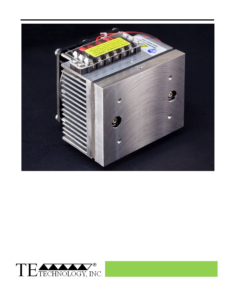
CP-031 Peltier-Thermoelectric Cold-Plate Cooler
• Heats as well as cools (when used with heat & cool / bipolar controller).
• Small, low-cost standard cold plate cooler.
• Provides effective, direct-contact cooling or heating.
• Powered by 12 VDC; its low power consumption makes it compatible with a wide
range of our temperature controllers.
• Can be used to heat to 70°C; High Temperature (HT) version is available for heating to
100°C.
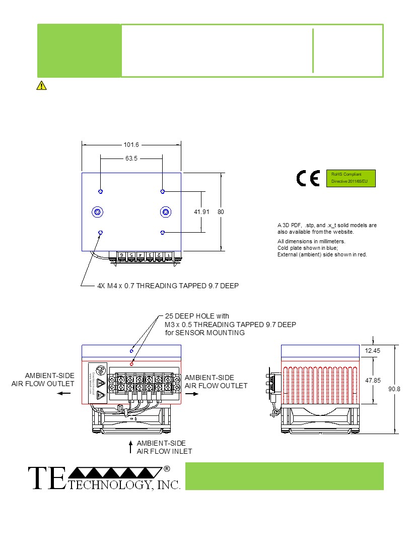
• Threaded holes are located in the cold plate for easy attachment of a temperature
sensor, interface plates, and other cooled plates.
• Can be customized for production-sized orders to meet your exact requirements.
• CE marked, RoHS compliant.
Expert Engineering, Precision Manufacturing:
Quality Thermal Solutions Delivered
NOTE: All specifications are subject to change without notice.
© 2023 TE Technology, Inc.
CP-031 16-NOV-2023 Page 1 of 8
Thermoelectric (TE) Power (typical)1,3 :
12 VDC at 4.3 A
NEMA Rating: NA
Thermoelectric (TE) Power (maximum)2,3 :
12 VDC at 5.4 A
CP-031
External (ambient) Fan Power:
12 VDC at 0.18 A
Specifications
Weight (kg):
0.9
External (ambient) Fan Noise:
34 dBA
Performance is based on unrestricted air flow to fans
and from air-flow outlets. Do not operate if the heat sink,
or cold plate exceeds 70 °C. Do not operate fans at air
temperatures below -20 °C or over 70 °C.
information before purchasing or using this product.
1Current, at steady-state, is rated at +25 °C ambient, +25 °C internal, maximum heat removal. At -17 °C cold plate, the typical steady-state current is 4.6 A.
2Current, at steady-state operation under-worst case conditions, is rated at -20 °C ambient, +70 °C internal, maximum heat removal.
3 Total current consumption is sum of TE current and Fan current.
Expert Engineering, Precision Manufacturing:
Quality Thermal Solutions Delivered
NOTE: All specifications are subject to change without notice.
© 2023 TE Technology, Inc.
CP-031 16-NOV-2023 Page 2 of 8
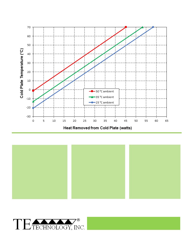
CP-031 Cooling Performance Graph
(removing heat from cold plate)
How to use the Performance Graph:
1. Select Performance Line
2. Select Plate Temperature
3. Determine Cooling Capacity
The diagonal lines represent cooling
Draw a horizontal line on the graph
The maximum amount of heat
performance at the indicated ambient
corresponding to the desired cold-
that the cooler can remove from
air temperature (intake temperature
plate temperature. Make the line
the cold plate is determined by
on the ambient-side fan). If the cooler
intersect with the performance line
the intersection point (determined
is to operate at a different ambient,
corresponding to the ambient
in the previous step). The cooler
then you must sketch in a new
temperature at which the cooler is to
will be able to maintain the
performance line. This can be drawn
operate.
desired temperature if the cooling
parallel to one of the existing lines,
capacity exceeds the heat load. If
using the distance between the
the heat load exceeds the cooling
existing lines as a scale to properly
capacity then a higher capacity
locate the new line.
cooler will be needed.
Example: You need to maintain the cold plate at 10 °C while in a 35 °C ambient. The cooler can remove a maximum of
approximately 15 W of heat from the cold plate. If the heat gain from the ambient plus anything else actively generating
heat exceeds this, you would need a cooler with a larger cooling capacity or multiple coolers.
Expert Engineering, Precision Manufacturing:
Quality Thermal Solutions Delivered
NOTE: All specifications are subject to change without notice.
© 2023 TE Technology, Inc.
CP-031 16-NOV-2023 Page 3 of 8
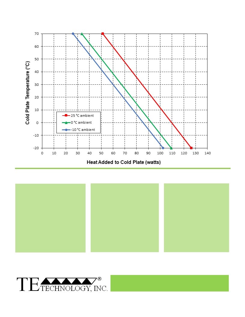
CP-031 Heating Performance Graph
(adding heat to cold plate)
How to use the Performance Graph:
1. Select Performance Line
2. Select Plate Temperature
3. Determine Heating Capacity
The diagonal lines represent heating
Draw a horizontal line on the graph
The maximum amount of heat
performance at the indicated ambient
corresponding to the desired cold-
that the cooler can add to the
air temperature (intake temperature
plate temperature. Make the line
cold plate is determined by the
on the ambient-side fan). If the cooler
intersect with the performance line
intersection point (determined in
is to operate at a different ambient,
corresponding to the ambient
the previous step). If the heat
then you must sketch in a new
temperature at which the cooler is
added to the cold plate (including
performance line. This can be drawn
to operate.
heat generated by equipment on
parallel to one of the existing lines,
the cold plate) is greater than the
using the distance between the
heat loss from the cold plate, then
existing lines as a scale to properly
the cooler will be able to heat to
locate the new line.
the desired temperature.
Example: You need to maintain the cold plate at 30 °C while in a 0 °C ambient. The cooler can add up to approximately
68 W of heat to the cold plate. If the heat dissipation from the cold plate to the ambient exceeds this (plus anything else
generating heat), you would need multiple coolers or a cooler with a larger heating capacity.
Expert Engineering, Precision Manufacturing:
Quality Thermal Solutions Delivered
NOTE: All specifications are subject to change without notice.
© 2023 TE Technology, Inc.
CP-031 16-NOV-2023 Page 4 of 8
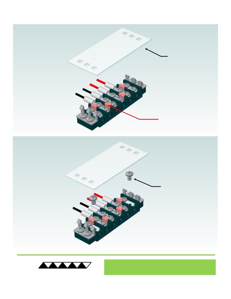
Terminal Block Configuration for Continuous Operation at Full Power
As-Shipped Configuration 1 of 2
1
REMOVE TERMINAL
BLOCK COVER
FOUR ELECTRICAL
JUMPERS INSTALLED
(ORIGINAL
CONFIGURATION)
2
LOOSEN TWO SCREWS
KEEP JUMPERS INSTALLED
® Expert Engineering, Precision Manufacturing:
Quality Thermal Solutions Delivered
TE
TECHNOLOGY, INC.
• cool@tetech.com • 231-929-3966 • 1590 Keane Drive • Traverse City, MI 49696
NOTE: All specifications are subject to change without notice.
© 2023 TE Technology, Inc.
CP-031 16-NOV-2023 Page 5 of 8
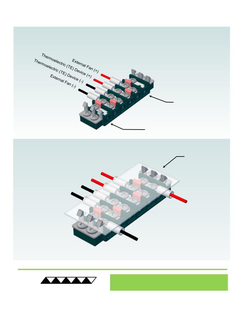
Terminal Block Configuration for Continuous Operation at Full Power
2 of 2
3
Power supply (+) Red Wire
to POSITION 6
Power supply (-) Black Wire
to POSITION 1
INSTALL WIRES,
4
TIGHTEN SCREWS
TO 1.0 N-M, AND
REPLACE COVER
® Expert Engineering, Precision Manufacturing:
Quality Thermal Solutions Delivered
TE
TECHNOLOGY, INC.
NOTE: All specifications are subject to change without notice.
© 2023 TE Technology, Inc.
CP-031 16-NOV-2023 Page 6 of 8
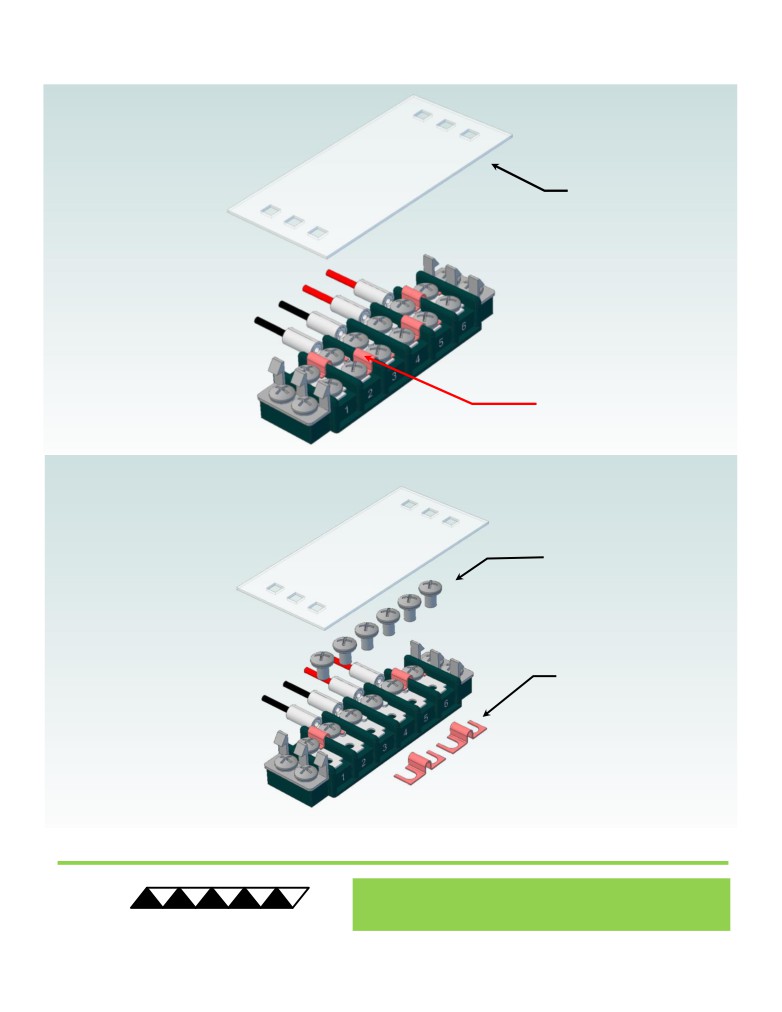
Terminal Block Configuration for Operation with Temperature Controller
1 of 2
1
REMOVE TERMINAL
BLOCK COVER
FOUR ELECTRICAL
JUMPERS INSTALLED
(ORIGINAL
CONFIGURATION)
2
LOOSEN SIX SCREWS
REMOVE TWO
ELECTRICAL JUMPERS
FROM 2-3 AND 4-5
® Expert Engineering, Precision Manufacturing:
Quality Thermal Solutions Delivered
TE
TECHNOLOGY, INC.
NOTE: All specifications are subject to change without notice.
© 2023 TE Technology, Inc.
CP-031 16-NOV-2023 Page 7 of 8
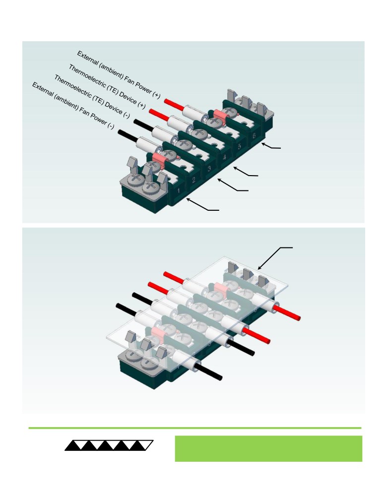
Terminal Block Configuration for Operation with Temperature Controller
2 of 2
3
Power supply (+) Red Wire
to POSITION 6
Temperature Controller (+) Red Wire
to POSITION 4
Temperature Controller (-) Black Wire
To POSITION 3
Power supply (-) Black Wire
to POSITION 1
INSTALL WIRES,
4
TIGHTEN SCREWS
TO 1.0 N-M, AND
REPLACE COVER
® Expert Engineering, Precision Manufacturing:
Quality Thermal Solutions Delivered
TE
TECHNOLOGY, INC.
NOTE: All specifications are subject to change without notice.
© 2023 TE Technology, Inc.
CP-031 16-NOV-2023 Page 8 of 8