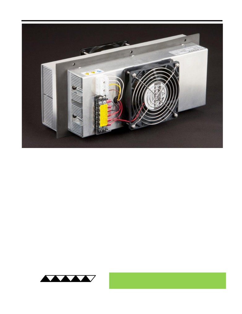
AC-220 Peltier-Thermoelectric Air Cooler
•
Ideal for medium to large electronics enclosures or refrigeration applications where a
large temperature difference is not required.
•
NEMA 4 protection: anodized external fins, environmentally sealed IP68 external fan,
and stainless steel finger guards.
•
Large cooling capacity in a compact size: 350 mm length x 150 mm width x 185 mm
thickness.
•
Removes 214 W of heat in a 32 °C ambient at a 0 °C temperature difference.
•
Internal fan blows air into the center of the enclosure so you can aim cooled air at
components that need the most cooling.
•
Heats as well as cools (when used with heat & cool / bipolar controller).
•
High quality dual ball bearing fans for long life; external fan is speed controllable and
has tachometer output.
•
Can easily be customized for production sized orders to meet your exact
requirements.
•
Includes integral thermostats (signal level) for over temperature protection using
power supply inhibit lines or temperature controller interlock features.
•
CE marked, RoHS compliant.
® Expert Engineering, Precision Manufacturing:
Quality Thermal Solutions Delivered
TE
TECHNOLOGY, INC.
NOTE: All specifications are subject to change without notice.
© 2018 TE Technology, Inc.
AC-220 6-FEB-2019 Page 1 of 9
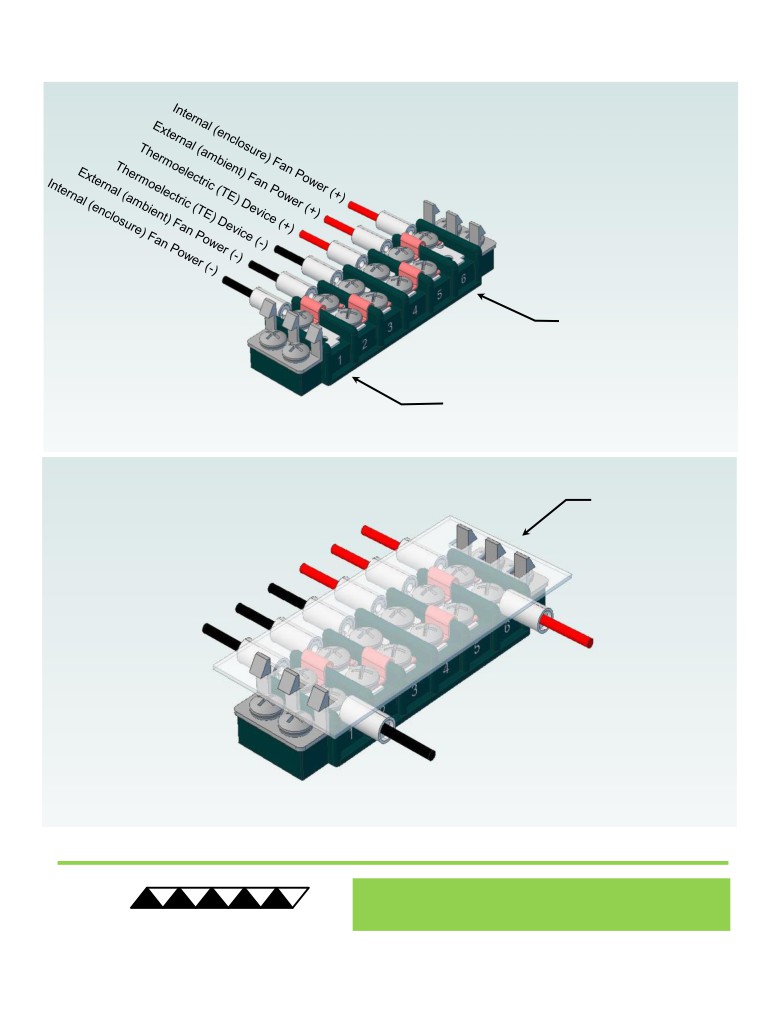
Thermoelectric (TE) Power (typical)1,3 :
24 VDC at 14.0 A
NEMA Rating: 4
Thermoelectric (TE) Power (maximum)2,3 :
24 VDC at 18.8 A
AC-220
External (ambient) Fan Power:
24 VDC at 1.50 A
Ext Fan Rating: IP68
Internal (enclosure) Fan Power:
24 VDC at 0.21 A
Specifications
External (ambient) Fan Noise:
64 dBA max - 33 dBA min
Weight (kg):
6.3
Internal (enclosure) Fan Noise:
44 dBA
Performance is based on unrestricted air flow to fans and
from air-flow outlets. Do not operate if the ambient,
enclosure air, heat sink, or cold sink temperatures exceed
70 °C. Do not operate fan at air temperatures below -20 °C
information before purchasing or using this product.
or above 70 °C.
1Current, at steady-state, is rated at +25 °C ambient, +25 °C internal, maximum heat removal. At 10 °C internal, the typical steady-state current is 13.8 A.
2Current, at steady-state operation under-worst case conditions, is rated at -20 °C ambient, +70 °C internal, maximum heat removal.
3Total current consumption is sum of TE current and Fan current.
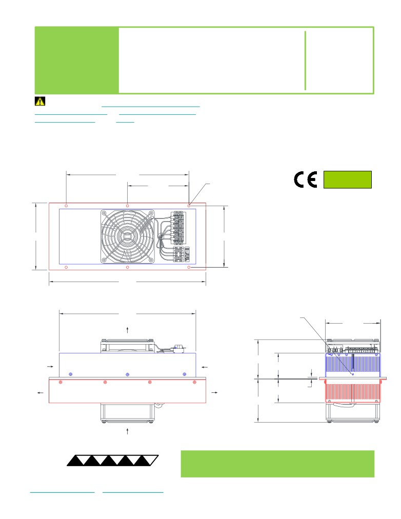
273.56
RoHS Compliant
6X Ø 5.59 THRU
Directive 2011/65/EU
136.78
A 3D PDF, .stp, and .sldprt solid models
are also available from the website. Contact
TE Technology for 3D solid models in other
149.6
136.91
formats.
All dimensions in millimeters.
Internal (enclosure) side shown in blue;
External (ambient) side shown in red.
349.8
304.8
25 DEEP HOLE with
M3 x 0.5 THREADING TAPPED 9.7 DEEP
for SENSOR MOUNTING
122.8
INTERNAL
(ENCLOSURE)-SIDE
AIR FLOW OUTLET
INTERNAL
INTERNAL
(ENCLOSURE)-SIDE
(ENCLOSURE)-SIDE
87.8
AIR FLOW INLET
AIR FLOW INLET
56.9
EXTERNAL
EXTERNAL
(AMBIENT)-SIDE
(AMBIENT)-SIDE
4.8
AIR FLOW OUTLET
AIR FLOW OUTLET
53.6
97.2
EXTERNAL
(AMBIENT)-SIDE
AIR FLOW ILNET
® Expert Engineering, Precision Manufacturing:
Quality Thermal Solutions Delivered
TE
TECHNOLOGY, INC.
NOTE: All specifications are subject to change without notice.
© 2018 TE Technology, Inc.
AC-220 6-FEB-2019 Page 2 of 9
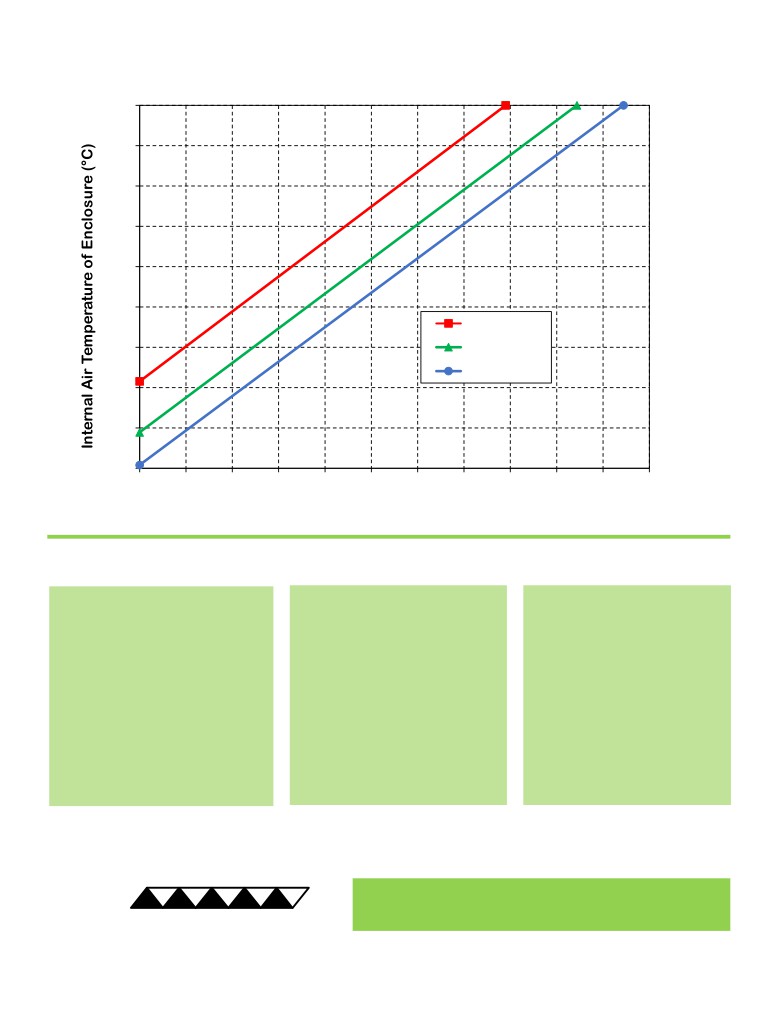
AC-220 Cooling Performance Graph
(removing heat from enclosure)
70
60
50
40
30
20
50 °C ambient
10
35 °C ambient
25 °C ambient
0
-10
-20
0
40
80
120
160
200
240
280
320
360
400
440
Heat Removed from Enclosure (watts)
How to use the Performance Graph:
1. Select Performance Line
2. Select Enclosure Temperature
3. Determine Cooling Capacity
The diagonal lines represent cooling
Draw a horizontal line on the graph
The maximum amount of heat
performance at the indicated ambient
corresponding to the desired internal
that the cooler can remove from
air temperature (intake temperature
air temperature of the enclosure.
the enclosure is determined by
on the ambient-side fan). If the cooler
Make the line intersect with the
the intersection point (determined
is to operate at a different ambient,
performance line corresponding to
in the previous step). The cooler
then you must sketch in a new
the ambient temperature at which
will be able to maintain the
performance line. This can be drawn
the cooler is to operate.
desired enclosure temperature if
parallel to one of the existing lines,
the cooling capacity exceeds the
using the distance between the
heat load. If the heat load
existing lines as a scale to properly
exceeds the cooling capacity then
locate the new line.
a higher capacity cooler will be
needed.
Example: You need to maintain the enclosure at 40 °C while in a 50 °C ambient. The cooler can remove a maximum of
approximately 175 W of heat from the enclosure. If the heat load (internally generated heat plus the heat gain through
insulation, solar, vapor condensation, etc.) in the enclosure exceeds this, you would need more coolers and/or a larger
cooler.
® Expert Engineering, Precision Manufacturing:
Quality Thermal Solutions Delivered
TE
TECHNOLOGY, INC.
NOTE: All specifications are subject to change without notice.
© 2018 TE Technology, Inc.
AC-220 6-FEB-2019 Page 3 of 9
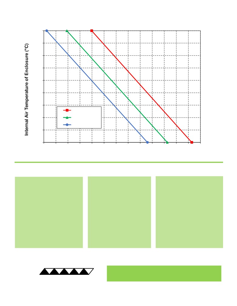
AC-220 Heating Performance Graph
(adding heat to enclosure)
70
60
50
40
30
20
10
25 °C ambient
0
0 °C ambient
-20 °C ambient
-10
-20
0
60
120
180
240
300
360
420
480
540
600
660
720
780
Heat Added to Enclosure (watts)
How to use the Performance Graph:
1. Select Performance Line
2. Select Enclosure Temperature
3. Determine Heating Capacity
The diagonal lines represent heating
Draw a horizontal line on the graph
The maximum amount of heat that
performance at the indicated ambient
corresponding to the desired
the cooler can add to the enclosure
air temperature (intake temperature
internal air temperature of the
is determined by the intersection
on the ambient-side fan). If the cooler
enclosure. Make the line intersect
point (determined in previous step).
is to operate at a different ambient,
with the performance line
If the heat added to the enclosure
then you must sketch in a new
corresponding to the ambient
(including heat generated by
performance line. This can be drawn
temperature at which the cooler is
equipment inside) is greater than
parallel to one of the existing lines,
to operate.
the enclosure’s heat loss, then the
using the distance between the
cooler will be able to heat to the
existing lines as a scale to properly
desired temperature. A higher
locate the new line.
capacity cooler will be needed if the
total heat added is less than the
enclosure’s heat loss.
Example: You need to maintain the enclosure at 30 °C while in a -20 °C ambient. The cooler can add up to
approximately 239 W of heat to the enclosure. If the heat dissipation from the enclosure to the ambient exceeds this
(plus anything else generating heat), you would need more coolers and/or a larger cooler.
® Expert Engineering, Precision Manufacturing:
Quality Thermal Solutions Delivered
TE
TECHNOLOGY, INC.
NOTE: All specifications are subject to change without notice.
© 2018 TE Technology, Inc.
AC-220 6-FEB-2019 Page 4 of 9
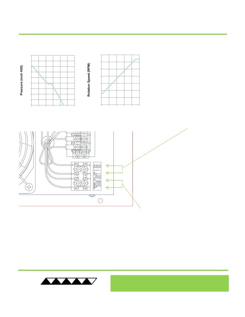
AC-220 External Fan and Thermostat Connections
1.8
7000
The external fan speed can be controlled
1.6
6000
using pulse width modulation at a
1.4
recommended 5KHz to 25 kHz frequency
5000
1.2
applied at terminal position 4 (SPD CTRL,
4000
brown wire). The TC-720
temperature
1.0
controller can be used to provide this
0.8
3000
PWM signal to reduce the audible noise at
0.6
2000
low cooling demands
(use
5400Hz
0.4
frequency setting). Electrical ground to
1000
0.2
terminal position 4 will reduce fan speed.
0.0
0
0
50
100 150 200 250 300
0
20
40
60
80
100
Terminal position
3 provides for a fan-
Airflow (CFM) at 100%
PWM Duty Cycle (%)
speed sensor, sending two pulses per
revolution. Consult with TE Technology if
you wish to use this feature.
Two thermostats are wired in series and
terminated at positions
1
and
2. One is
mounted mounted internally on the heat sink
and one externally on the cold sink. The
thermostats are normally closed, open at 75
°C +/-5 °C, and automatically reclose at 60 °C
+/-7
°C. These can be wired to a power
supply’s remote switch or the TC-720
temperature controller’s interlock to shut off
output power in the event of an over-
temperature condition. The electrical contacts
are rated for SIGNAL LEVEL ONLY.
Contacts are gold-plated silver. DO NOT
USE AS A TEMPERATURE CONTROL FOR
THE COOLER.
Thermostat Contact Electrical Ratings:
•
48VDC, 1 Amp, Resistive, 30,000 Cycles
•
120VAC, 1 Amp, Resistive, 30,000 Cycles
•
5VDC, 20mA, Resistive, 100,000 Cycles
® Expert Engineering, Precision Manufacturing:
Quality Thermal Solutions Delivered
TE
TECHNOLOGY, INC.
NOTE: All specifications are subject to change without notice.
© 2018 TE Technology, Inc.
AC-220 6-FEB-2019 Page 5 of 9
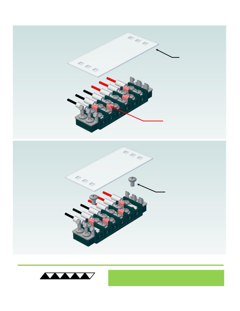
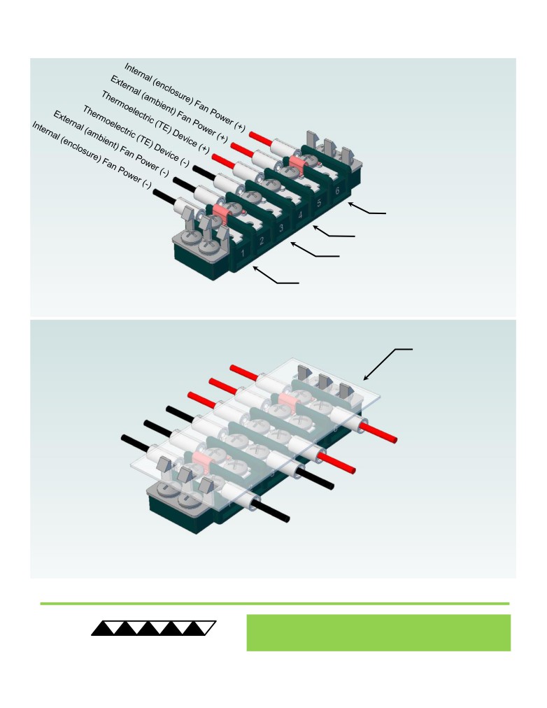
Terminal Block Configuration for Continuous Operation at Full Power
As-Shipped Configuration 1 of 2
1
REMOVE TERMINAL
BLOCK COVER
FOUR ELECTRICAL
JUMPERS INSTALLED
(ORIGINAL
CONFIGURATION)
2
LOOSEN TWO SCREWS
KEEP JUMPERS INSTALLED
® Expert Engineering, Precision Manufacturing:
Quality Thermal Solutions Delivered
TE
TECHNOLOGY, INC.
NOTE: All specifications are subject to change without notice.
© 2018 TE Technology, Inc.
AC-220 6-FEB-2019 Page 6 of 9
Terminal Block Configuration for Continuous Operation at Full Power
2 of 2
3
Power supply (+) Red Wire
to POSITION 6
Power supply (-) Black Wire
to POSITION 1
INSTALL WIRES,
4
TIGHTEN SCREWS
TO 1.0 N-M, AND
REPLACE COVER
® Expert Engineering, Precision Manufacturing:
Quality Thermal Solutions Delivered
TE
TECHNOLOGY, INC.
NOTE: All specifications are subject to change without notice.
© 2018 TE Technology, Inc.
AC-220 6-FEB-2019 Page 7 of 9
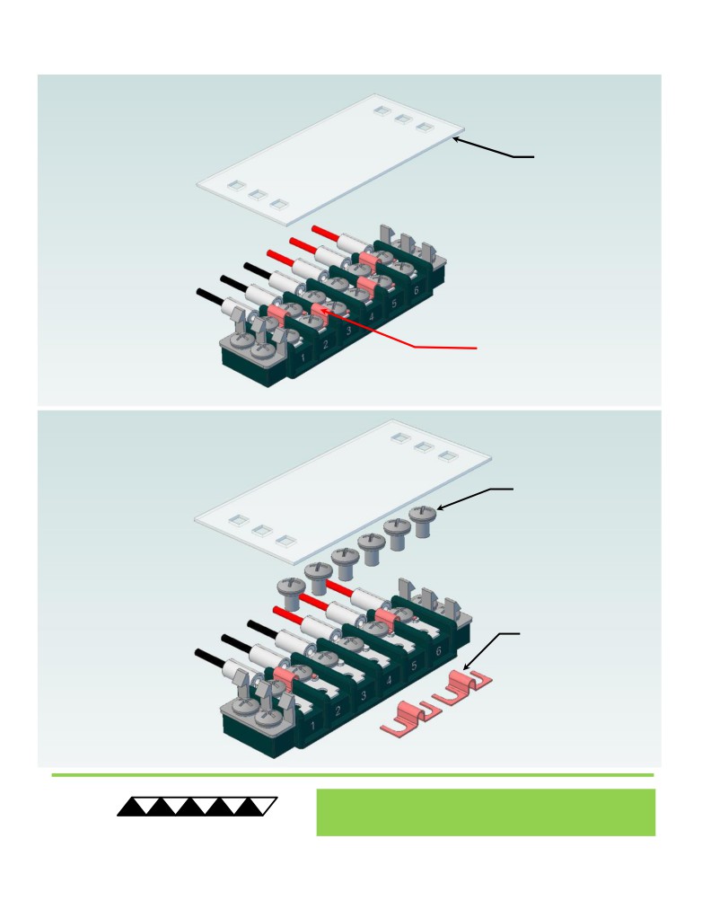
Terminal Block Configuration for Operation with Temperature Controller
1 of 2
1
REMOVE TERMINAL
BLOCK COVER
FOUR ELECTRICAL
JUMPERS INSTALLED
(ORIGINAL CONFIGURATION)
2
LOOSEN SIX SCREWS
REMOVE TWO
ELECTRICAL JUMPERS
FROM 2-3 AND 4-5
® Expert Engineering, Precision Manufacturing:
Quality Thermal Solutions Delivered
TE
TECHNOLOGY, INC.
NOTE: All specifications are subject to change without notice.
© 2018 TE Technology, Inc.
AC-220 6-FEB-2019 Page 8 of 9
Terminal Block Configuration for Operation with Temperature Controller
2 of 2
3
Power supply (+) Red Wire
to POSITION 6
Temperature Controller (+) Red Wire
to POSITION 4
Temperature Controller (-) Black Wire
To POSITION 3
Power supply (-) Black Wire
to POSITION 1
INSTALL WIRES,
4
TIGHTEN SCREWS
TO 1.0 N-M, AND
REPLACE COVER
® Expert Engineering, Precision Manufacturing:
Quality Thermal Solutions Delivered
TE
TECHNOLOGY, INC.
NOTE: All specifications are subject to change without notice.
© 2018 TE Technology, Inc.
AC-220 6-FEB-2019 Page 9 of 9