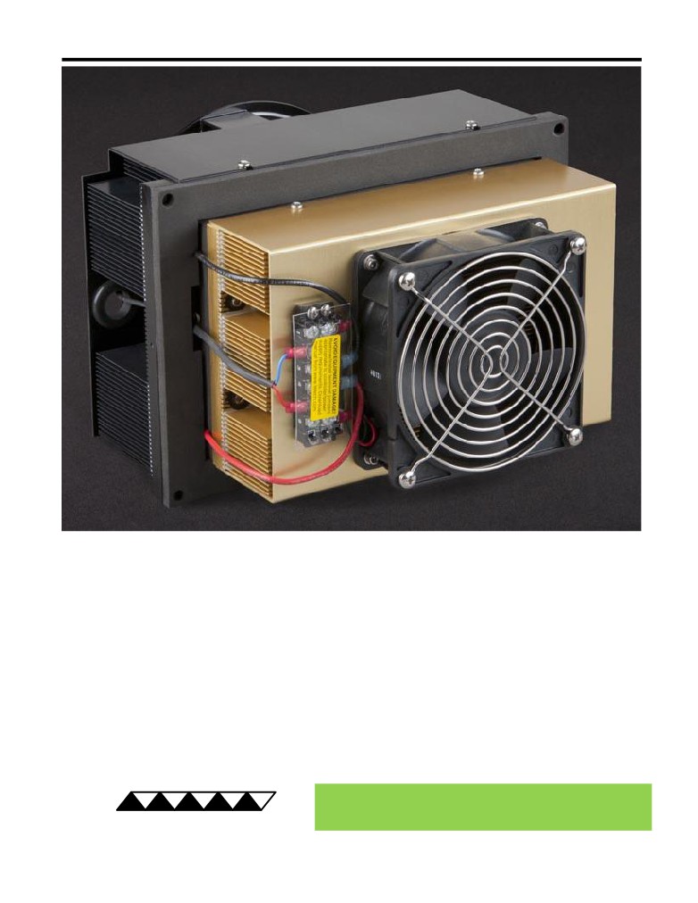
AC-140 Peltier-Thermoelectric Air Cooler
• Ideal for telecommunications equipment and electronic enclosures where the cooler’s
power supply is located inside the enclosure.
• Can be used with a wide variety of TE Technology temperature controllers.
• Anodized heat sink and environmentally sealed external fan.
• Maintains enclosure at NEMA 4 rating.
• High coefficient of performance at low temperature differences.
• Input wires are routed on the cold side of the cooler, making it easy to power via
wiring from inside the enclosure.
• Can easily be customized for production sized orders to meet your exact
requirements.
• CE marked, RoHS compliant.
® Expert Engineering, Precision Manufacturing:
Quality Thermal Solutions Delivered
TE
TECHNOLOGY, INC.
NOTE: All specifications are subject to change without notice.
© 2018 TE Technology, Inc.
AC-140 6-FEB-2019 Page 1 of 8
Thermoelectric (TE) Power (typical)1,3 :
24 VDC at 4.7 A
NEMA Rating: 4
Thermoelectric (TE) Power (maximum)2,3 :
24 VDC at 6.9 A
AC-140
External (ambient) Fan Power:
24 VDC at 0.65 A
Ext Fan Rating: IP68
Internal (enclosure) Fan Power:
24 VDC at 0.22 A
Specifications
External (ambient) Fan Noise:
55 dBA
Weight (kg):
7.8
Internal (enclosure) Fan Noise:
39 dBA
Performance is based on unrestricted air flow to fans and
from air-flow outlets. Do not operate if the ambient,
enclosure air, heat sink, or cold sink temperatures exceed
information before purchasing or using this product.
70 °C. Do not operate fan at air temperatures below -20 °C
or above 70 °C.
1Current is rated at +25 °C ambient, +25 °C internal, maximum heat removal. At -5.7 °C internal, the typical current is 4.2 A.
2Current, at steady-state operation under-worst case conditions, is rated at -20 °C ambient, +70 °C internal, maximum heat removal.
3Total current consumption is sum of TE current and Fan current.
259.1
246.4
6.4
215.9
21.6
RoHS Compliant
Directive 2011/65/EU
175.8
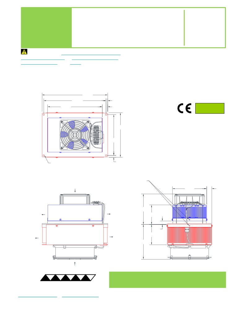
A 3D PDF, .stp, and .sldprt solid models
are also available from the website. Contact
161
TE Technology for 3D solid models in other
formats.
All dimensions in millimeters.
Internal (enclosure) side shown in blue;
External (ambient) side shown in red.
7.4
4X Ø6.35 THRU
25 DEEP HOLE with
M3 x 0.5 THREADING TAPPED 9.7 DEEP
for SENSOR MOUNTING
INTERNAL
(ENCLOSURE)-SIDE
135.4
20.2
AIR FLOW INLET
1
3
4
6
INTERNAL
INTERNAL
(ENCLOSURE)-SIDE
(ENCLOSURE)-SIDE
120.6
AIR FLOW OUTLET
AIR FLOW OUTLET
77
13.8
EXTERNAL
EXTERNAL
(AMBIENT)-SIDE
(AMBIENT)-SIDE
AIR FLOW OUTLET
80.3
AIR FLOW OUTLET
137.6
EXTERNAL
(AMBIENT)-SIDE
AIR FLOW INLET
® Expert Engineering, Precision Manufacturing:
Quality Thermal Solutions Delivered
TE
TECHNOLOGY, INC.
NOTE: All specifications are subject to change without notice.
© 2018 TE Technology, Inc.
AC-140 6-FEB-2019 Page 2 of 8
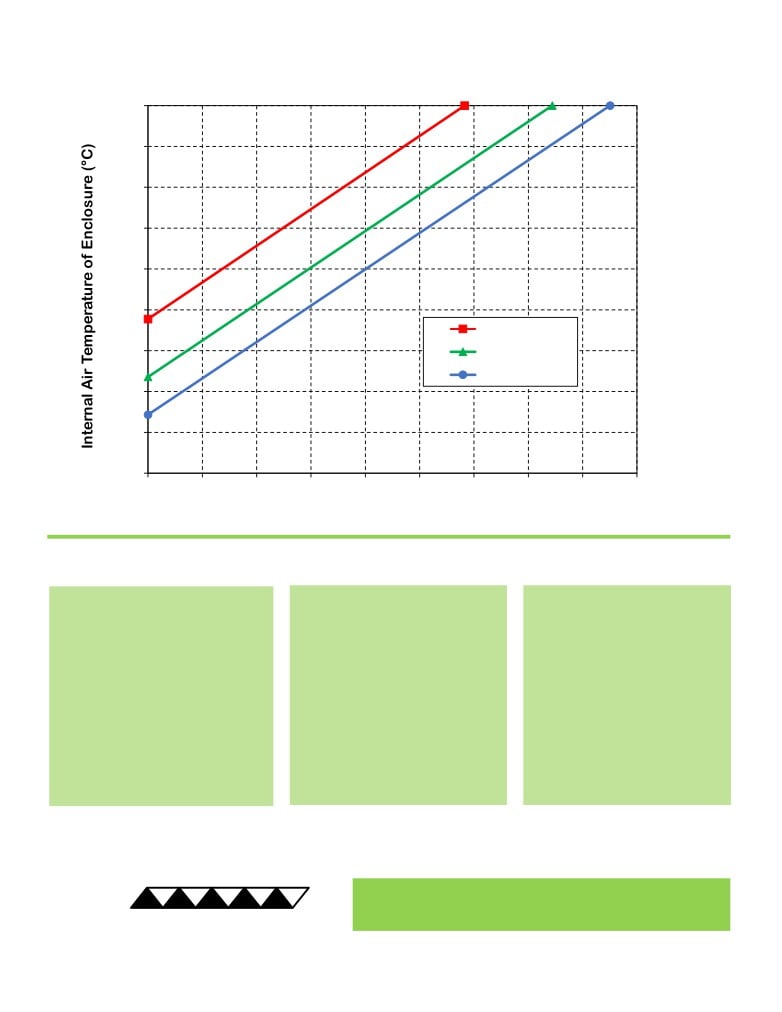
AC-140 Cooling Performance Graph
(removing heat from enclosure)
70
60
50
40
30
20
50 °C ambient
10
35 °C ambient
25 °C ambient
0
-10
-20
0
40
80
120
160
200
240
280
320
360
Heat Removed from Enclosure (watts)
How to use the Performance Graph:
1. Select Performance Line
2. Select Enclosure Temperature
3. Determine Cooling Capacity
The diagonal lines represent cooling
Draw a horizontal line on the graph
The maximum amount of heat
performance at the indicated ambient
corresponding to the desired internal
that the cooler can remove from
air temperature (intake temperature
air temperature of the enclosure.
the enclosure is determined by
on the ambient-side fan). If the cooler
Make the line intersect with the
the intersection point (determined
is to operate at a different ambient,
performance line corresponding to
in the previous step). The cooler
then you must sketch in a new
the ambient temperature at which
will be able to maintain the
performance line. This can be drawn
the cooler is to operate.
desired enclosure temperature if
parallel to one of the existing lines,
the cooling capacity exceeds the
using the distance between the
heat load. If the heat load
existing lines as a scale to properly
exceeds the cooling capacity then
locate the new line.
a higher capacity cooler will be
needed.
Example: You need to maintain the enclosure at 15 °C while in a 25 °C ambient. The cooler can remove a maximum of
approximately 95 W of heat from the enclosure. If the heat load (internally generated heat plus the heat gain through
insulation, solar, vapor condensation, etc.) in the enclosure exceeds this, you would need more coolers and/or a larger
cooler.
® Expert Engineering, Precision Manufacturing:
Quality Thermal Solutions Delivered
TE
TECHNOLOGY, INC.
NOTE: All specifications are subject to change without notice.
© 2018 TE Technology, Inc.
AC-140 6-FEB-2019 Page 3 of 8
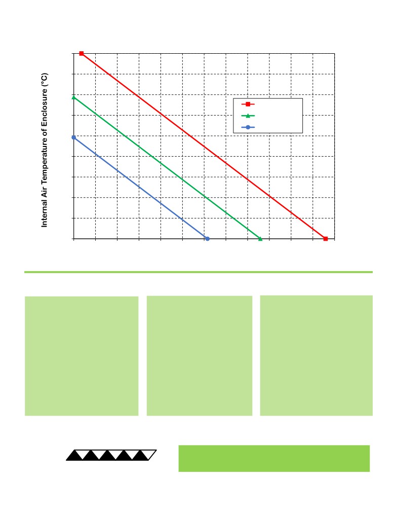
AC-140 Heating Performance Graph
(adding heat to enclosure)
70
60
50
25 °C ambient
40
0 °C ambient
-20 °C ambient
30
20
10
0
-10
-20
0
40
80
120
160
200
240
280
320
360
400
440
480
Heat Added to Enclosure (watts)
How to use the Performance Graph:
1. Select Performance Line
2. Select Enclosure Temperature
3. Determine Heating Capacity
The diagonal lines represent heating
Draw a horizontal line on the graph
The maximum amount of heat that
performance at the indicated ambient
corresponding to the desired
the cooler can add to the enclosure
air temperature (intake temperature
internal air temperature of the
is determined by the intersection
on the ambient-side fan). If the cooler
enclosure. Make the line intersect
point (determined in previous step).
is to operate at a different ambient,
with the performance line
If the heat added to the enclosure
then you must sketch in a new
corresponding to the ambient
(including heat generated by
performance line. This can be drawn
temperature at which the cooler is
equipment inside) is greater than the
parallel to one of the existing lines,
to operate.
enclosure’s heat loss, then the
using the distance between the
cooler will be able to heat to the
existing lines as a scale to properly
desired temperature. A higher
locate the new line.
capacity cooler will be needed if the
total heat added is less than the
enclosure’s heat loss.
Example: You need to maintain the enclosure at 10 °C while in a 0 °C ambient. The cooler can add a maximum of
approximately 193 W of heat to the enclosure. If the heat dissipation from the enclosure exceeds this (plus anything
else generating heat), you would need more coolers and/or a larger cooler.
® Expert Engineering, Precision Manufacturing:
Quality Thermal Solutions Delivered
TE
TECHNOLOGY, INC.
NOTE: All specifications are subject to change without notice.
© 2018 TE Technology, Inc.
AC-140 6-FEB-2019 Page 4 of 8
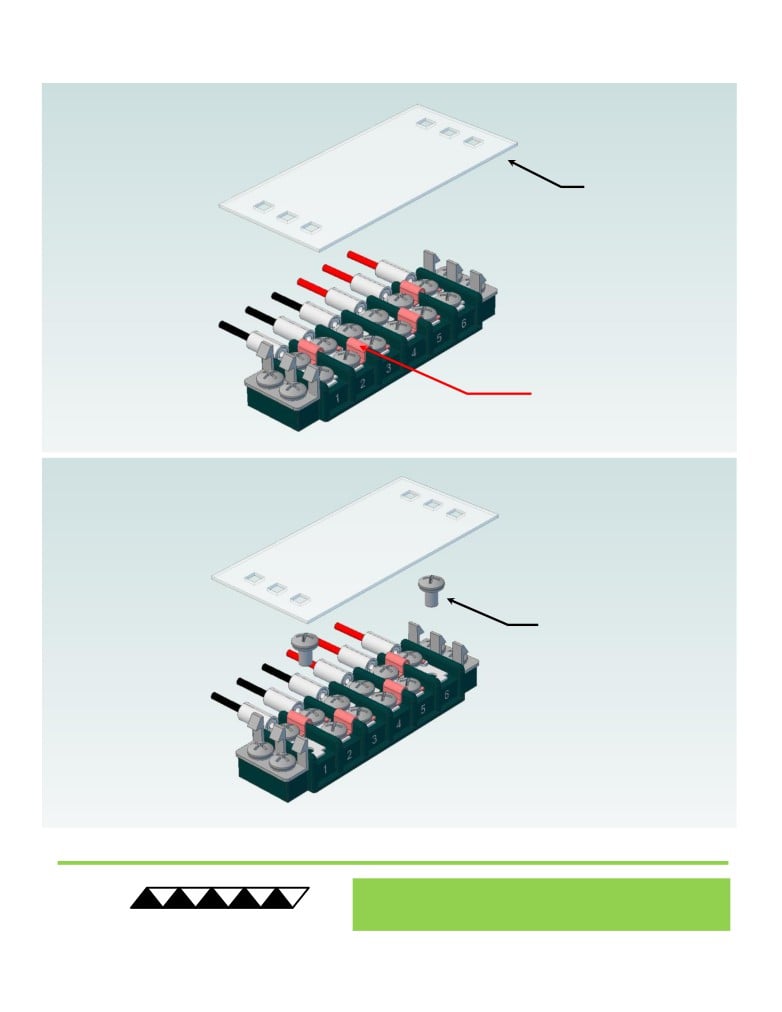
Terminal Block Configuration for Continuous Operation at Full Power
As-Shipped Configuration 1 of 2
1
REMOVE TERMINAL
BLOCK COVER
FOUR ELECTRICAL
JUMPERS INSTALLED
(ORIGINAL
CONFIGURATION)
2
LOOSEN TWO SCREWS
KEEP JUMPERS INSTALLED
® Expert Engineering, Precision Manufacturing:
Quality Thermal Solutions Delivered
TE
TECHNOLOGY, INC.
NOTE: All specifications are subject to change without notice.
© 2018 TE Technology, Inc.
AC-140 6-FEB-2019 Page 5 of 8
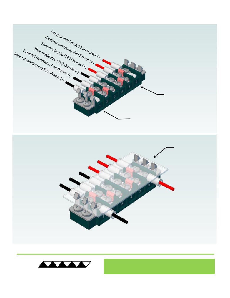
Terminal Block Configuration for Continuous Operation at Full Power
2 of 2
3
Power supply (+) Red Wire
to POSITION 6
Power supply (-) Black Wire
to POSITION 1
INSTALL WIRES,
4
TIGHTEN SCREWS
TO 1.0 N-M, AND
REPLACE COVER
® Expert Engineering, Precision Manufacturing:
Quality Thermal Solutions Delivered
TE
TECHNOLOGY, INC.
NOTE: All specifications are subject to change without notice.
© 2018 TE Technology, Inc.
AC-140 6-FEB-2019 Page 6 of 8
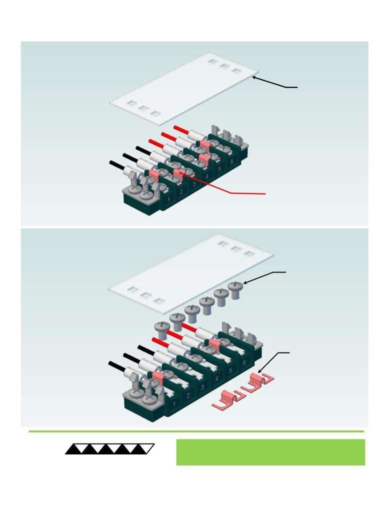
Terminal Block Configuration for Operation with Temperature Controller
1 of 2
1
REMOVE TERMINAL
BLOCK COVER
FOUR ELECTRICAL
JUMPERS INSTALLED
(ORIGINAL CONFIGURATION)
2
LOOSEN SIX SCREWS
REMOVE TWO
ELECTRICAL JUMPERS
FROM 2-3 AND 4-5
® Expert Engineering, Precision Manufacturing:
Quality Thermal Solutions Delivered
TE
TECHNOLOGY, INC.
NOTE: All specifications are subject to change without notice.
© 2018 TE Technology, Inc.
AC-140 6-FEB-2019 Page 7 of 8
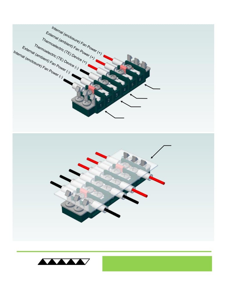
Terminal Block Configuration for Operation with Temperature Controller
2 of 2
3
Power supply (+) Red Wire
to POSITION 6
Temperature Controller (+) Red Wire
to POSITION 4
Temperature Controller (-) Black Wire
To POSITION 3
Power supply (-) Black Wire
to POSITION 1
INSTALL WIRES,
4
TIGHTEN SCREWS
TO 1.0 N-M, AND
REPLACE COVER
® Expert Engineering, Precision Manufacturing:
Quality Thermal Solutions Delivered
TE
TECHNOLOGY, INC.
NOTE: All specifications are subject to change without notice.
© 2018 TE Technology, Inc.
AC-140 6-FEB-2019 Page 8 of 8