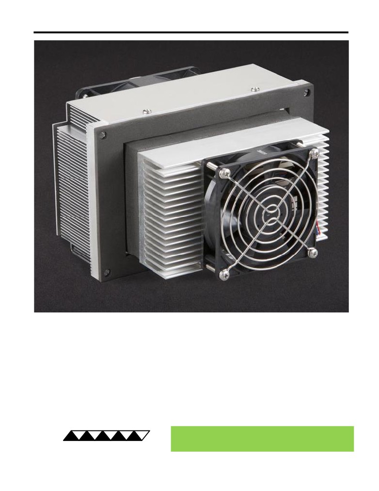
AC-073 Peltier-Thermoelectric Air Cooler
• Ideal for small to medium-sized refrigerators and biomedical equipment; good for
electronic enclosures, as well.
• High-efficiency heat sink provides good cooling capacity cooling in a compact space.
• The low fin density cold sink allows the condensate to easily drain off in applications
where water vapor condensation will occur.
• Maintains enclosure at NEMA 12 rating, but can be customized for NEMA 4.
• Can easily be customized for production sized orders to meet your exact
requirements.
• CE marked, RoHS compliant.
® Expert Engineering, Precision Manufacturing:
Quality Thermal Solutions Delivered
TE
TECHNOLOGY, INC.
NOTE: All specifications are subject to change without notice.
© 2018 TE Technology, Inc.
AC-073 6-FEB-2019 Page 1 of 8
Thermoelectric (TE) Power (typical)1,3 :
24 VDC at 9.0 A
Thermoelectric (TE) Power (maximum)2,3 :
24 VDC at 10.8 A
NEMA Rating: 12
AC-073
External (ambient) Fan Power:
24 VDC at 0.50 A
Internal (enclosure) Fan Power:
24 VDC at 0.15 A
Specifications
Weight (kg):
3.6
External (ambient) Fan Noise:
49 dBA
Internal (enclosure) Fan Noise:
39 dBA
Performance is based on unrestricted air flow to fans and
from air-flow outlets. Do not operate if the ambient,
enclosure air, heat sink, or cold sink temperatures exceed
70 °C. Do not operate fan at air temperatures below -20 °C
information before purchasing or using this product.
or above 70 °C.
1Current, at steady-state, is rated at +25 °C ambient, +25 °C internal, maximum heat removal. At -10 °C internal, the typical steady-state current is 8.9 A.
2Current, at steady-state operation under-worst case conditions, is rated at -20 °C ambient, +70 °C internal, maximum heat removal.
3Total current consumption is sum of TE current and Fan current.
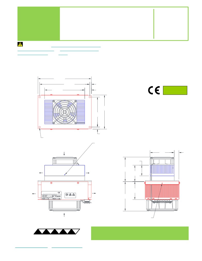
203.2
190.5
6.4
RoHS Compliant
152.4
25.4
Directive 2011/65/EU
130
A 3D PDF, .stp, and .sldprt solid models
are also available from the website. Contact
114.3
TE Technology for 3D solid models in other
formats.
All dimensions in millimeters.
Internal (enclosure) side shown in blue;
External (ambient) side shown in red.
7.9
4X Ø6.4 THRU
25 DEEP HOLE with
M3 x 0.5 THREADING TAPPED 9.7 DEEP
for SENSOR MOUNTING
INTERNAL
(ENCLOSURE)-SIDE
92
17.5
AIR FLOW INLET
40.6
INTERNAL
INTERNAL
(ENCLOSURE)-SIDE
(ENCLOSURE)-SIDE
93.2
AIR FLOW OUTLET
AIR FLOW OUTLET
62.3
EXTERNAL
EXTERNAL
(AMBIENT)-SIDE
(AMBIENT)-SIDE
AIR FLOW OUTLET
AIR FLOW OUTLET
68.6
Download manual
112.2
EXTERNAL
(AMBIENT)-SIDE
25 DEEP HOLE with
AIR FLOW INLET
M3 x 0.5 THREADING TAPPED 9.7 DEEP
for SENSOR MOUNTING
® Expert Engineering, Precision Manufacturing:
Quality Thermal Solutions Delivered
TE
TECHNOLOGY, INC.
NOTE: All specifications are subject to change without notice.
© 2018 TE Technology, Inc.
AC-073 6-FEB-2019 Page 2 of 8
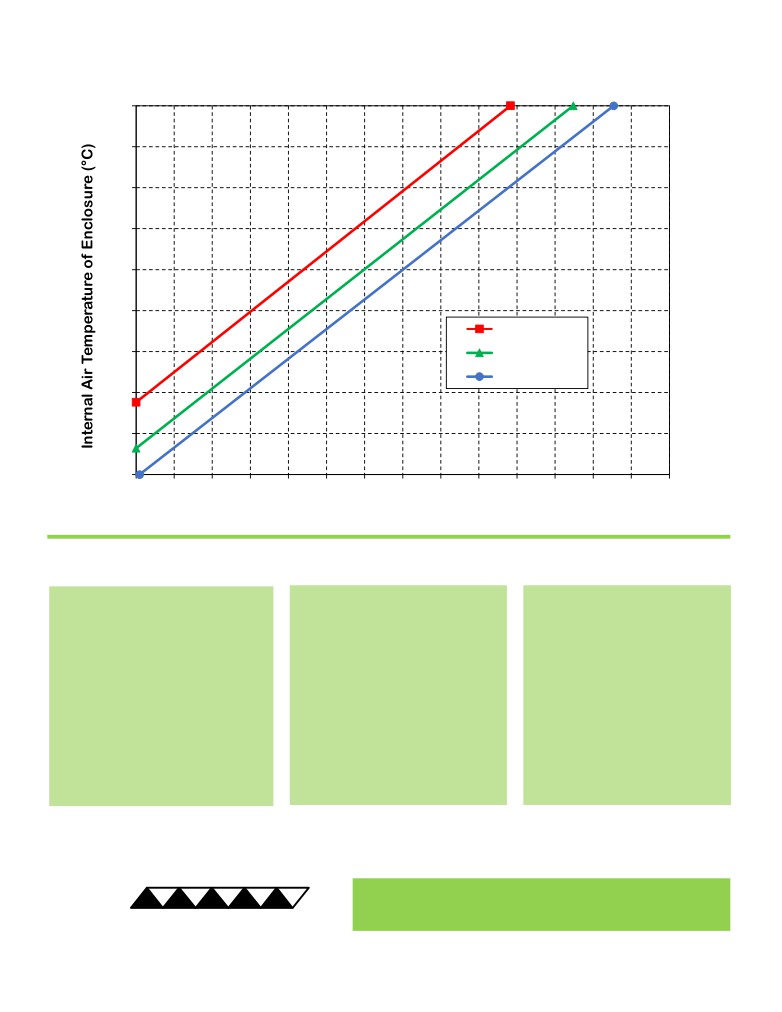
AC-073 Cooling Performance Graph
(removing heat from enclosure)
70
60
50
40
30
20
50 °C ambient
10
35 °C ambient
25 °C ambient
0
-10
-20
0
10
20
30
40
50
60
70
80
90
100
110
120
130
140
Heat Removed from Enclosure (watts)
How to use the Performance Graph:
1. Select Performance Line
2. Select Enclosure Temperature
3. Determine Cooling Capacity
The diagonal lines represent cooling
Draw a horizontal line on the graph
The maximum amount of heat
performance at the indicated ambient
corresponding to the desired internal
that the cooler can remove from
air temperature (intake temperature
air temperature of the enclosure.
the enclosure is determined by
on the ambient-side fan). If the cooler
Make the line intersect with the
the intersection point (determined
is to operate at a different ambient,
performance line corresponding to
in the previous step). The cooler
then you must sketch in a new
the ambient temperature at which
will be able to maintain the
performance line. This can be drawn
the cooler is to operate.
desired enclosure temperature if
parallel to one of the existing lines,
the cooling capacity exceeds the
using the distance between the
heat load. If the heat load
existing lines as a scale to properly
exceeds the cooling capacity then
locate the new line.
a higher capacity cooler will be
needed.
Example: You need to maintain the enclosure at 40 °C while in a 50 °C ambient. The cooler can remove a maximum of
approximately 57 W of heat from the enclosure. If the heat load (internally generated heat plus the heat gain through
insulation, solar, vapor condensation, etc.) in the enclosure exceeds this, you would need more coolers and/or a larger
cooler.
® Expert Engineering, Precision Manufacturing:
Quality Thermal Solutions Delivered
TE
TECHNOLOGY, INC.
NOTE: All specifications are subject to change without notice.
© 2018 TE Technology, Inc.
AC-073 6-FEB-2019 Page 3 of 8
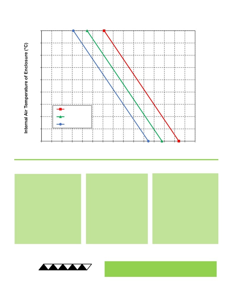
AC-073 Heating Performance Graph
(adding heat to enclosure)
70
60
50
40
30
20
10
25 °C ambient
0
0 °C ambient
-20 °C ambient
-10
-20
0
20
40
60
80
100
120
140
160
180
200
220
240
260
280
300
Heat Added to Enclosure (watts)
How to use the Performance Graph:
1. Select Performance Line
2. Select Enclosure Temperature
3. Determine Heating Capacity
The diagonal lines represent heating
Draw a horizontal line on the graph
The maximum amount of heat that
performance at the indicated ambient
corresponding to the desired
the cooler can add to the enclosure
air temperature (intake temperature
internal air temperature of the
is determined by the intersection
on the ambient-side fan). If the cooler
enclosure. Make the line intersect
point (determined in previous step).
is to operate at a different ambient,
with the performance line
If the heat added to the enclosure
then you must sketch in a new
corresponding to the ambient
(including heat generated by
performance line. This can be drawn
temperature at which the cooler is
equipment inside) is greater than the
parallel to one of the existing lines,
to operate.
enclosure’s heat loss, then the
using the distance between the
cooler will be able to heat to the
existing lines as a scale to properly
desired temperature. A higher
locate the new line.
capacity cooler will be needed if the
total heat added is less than the
enclosure’s heat loss.
Example: You need to maintain the enclosure at 30 °C while in a -20 °C ambient. The cooler can add a maximum of
approximately 127 W of heat to the enclosure. If the heat dissipation from the enclosure exceeds this (plus anything
else generating heat), you would need more coolers and/or a larger cooler.
® Expert Engineering, Precision Manufacturing:
Quality Thermal Solutions Delivered
TE
TECHNOLOGY, INC.
NOTE: All specifications are subject to change without notice.
© 2018 TE Technology, Inc.
AC-073 6-FEB-2019 Page 4 of 8
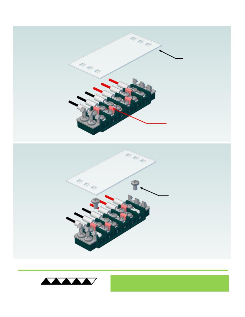
Terminal Block Configuration for Continuous Operation at Full Power
As-Shipped Configuration 1 of 2
1
REMOVE TERMINAL
BLOCK COVER
FOUR ELECTRICAL
JUMPERS INSTALLED
(ORIGINAL
CONFIGURATION)
2
LOOSEN TWO SCREWS
KEEP JUMPERS INSTALLED
® Expert Engineering, Precision Manufacturing:
Quality Thermal Solutions Delivered
TE
TECHNOLOGY, INC.
NOTE: All specifications are subject to change without notice.
© 2018 TE Technology, Inc.
AC-073 6-FEB-2019 Page 5 of 8
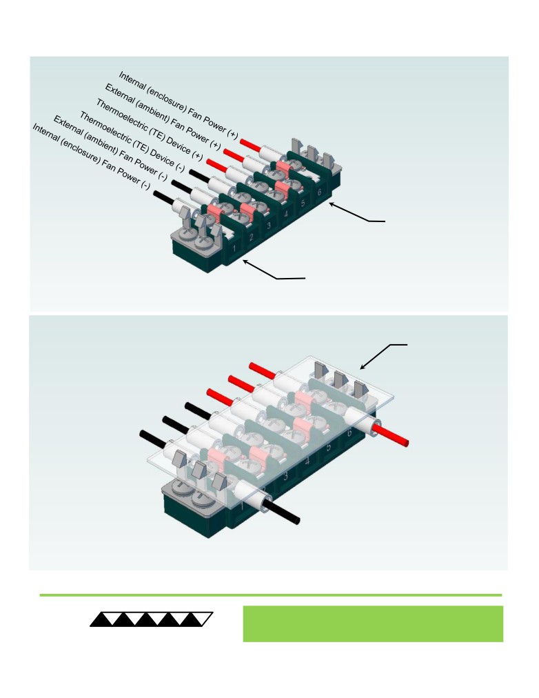
Terminal Block Configuration for Continuous Operation at Full Power
2 of 2
3
Power supply (+) Red Wire
to POSITION 6
Power supply (-) Black Wire
to POSITION 1
INSTALL WIRES,
4
TIGHTEN SCREWS
TO 1.0 N-M, AND
REPLACE COVER
® Expert Engineering, Precision Manufacturing:
Quality Thermal Solutions Delivered
TE
TECHNOLOGY, INC.
NOTE: All specifications are subject to change without notice.
© 2018 TE Technology, Inc.
AC-073 6-FEB-2019 Page 6 of 8
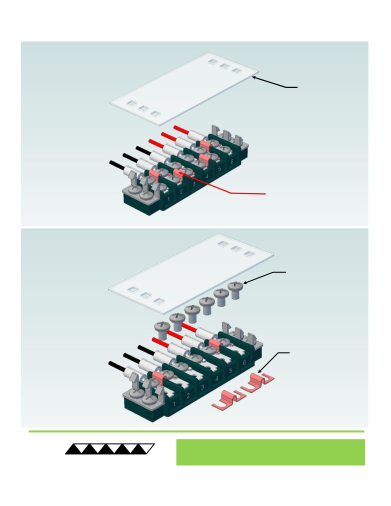
Terminal Block Configuration for Operation with Temperature Controller
1 of 2
1
REMOVE TERMINAL
BLOCK COVER
FOUR ELECTRICAL
JUMPERS INSTALLED
(ORIGINAL CONFIGURATION)
2
LOOSEN SIX SCREWS
REMOVE TWO
ELECTRICAL JUMPERS
FROM 2-3 AND 4-5
® Expert Engineering, Precision Manufacturing:
Quality Thermal Solutions Delivered
TE
TECHNOLOGY, INC.
NOTE: All specifications are subject to change without notice.
© 2018 TE Technology, Inc.
AC-073 6-FEB-2019 Page 7 of 8
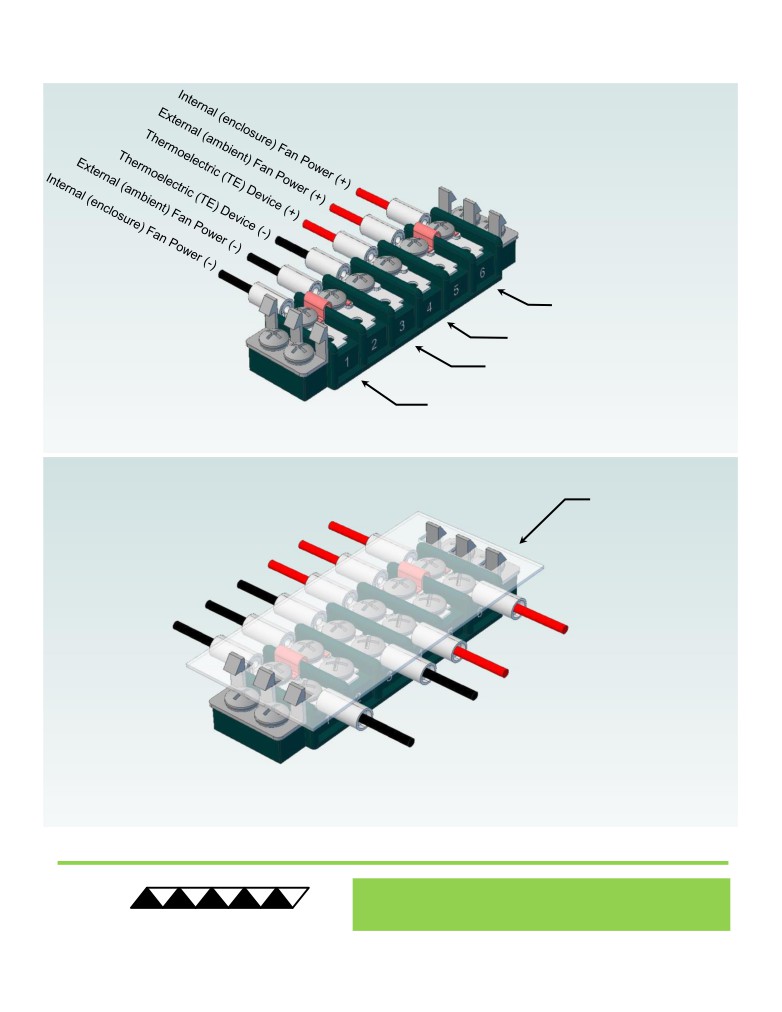
Terminal Block Configuration for Operation with Temperature Controller
2 of 2
3
Power supply (+) Red Wire
to POSITION 6
Temperature Controller (+) Red Wire
to POSITION 4
Temperature Controller (-) Black Wire
To POSITION 3
Power supply (-) Black Wire
to POSITION 1
INSTALL WIRES,
4
TIGHTEN SCREWS
TO 1.0 N-M, AND
REPLACE COVER
® Expert Engineering, Precision Manufacturing:
Quality Thermal Solutions Delivered
TE
TECHNOLOGY, INC.
NOTE: All specifications are subject to change without notice.
© 2018 TE Technology, Inc.
AC-073 6-FEB-2019 Page 8 of 8