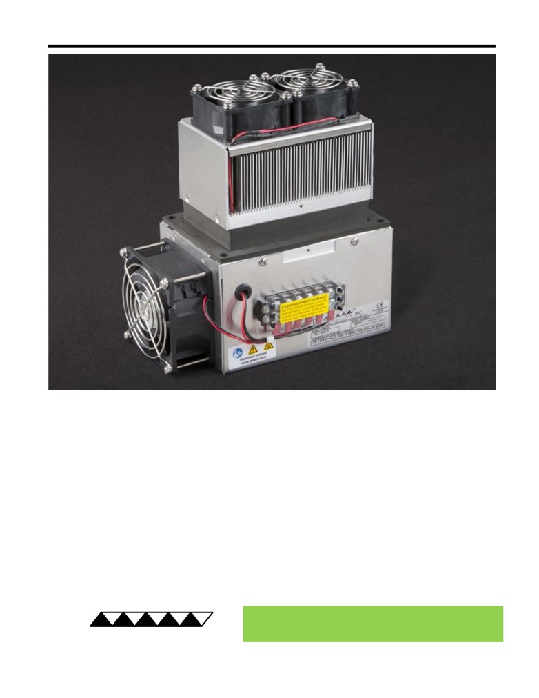
AC-053 Peltier-Thermoelectric Air Cooler
• Ideal for small enclosure refrigeration containing items that can not be cooled
through direct contact.
• External heat sink air flow is directed along the length of the heat sink fins (in one
end, out opposite end) providing a different option for routing air flow as compared
to TE Technology’s other standard air coolers.
• One of the two cold-side (internal) air exit paths can be blocked with only a minimal
impact on cooling performance, providing more mounting options in tight spaces.
• Low external fan noise (39 dBA) is beneficial in laboratory instrumentation.
• Threaded holes are located in the bases of the heat sink plates for easy attachment
of a temperature sensor.
• High-temperature versions and other customizations are available for production
volumes.
• CE marked, RoHS compliant.
® Expert Engineering, Precision Manufacturing:
Quality Thermal Solutions Delivered
TE
TECHNOLOGY, INC.
NOTE: All specifications are subject to change without notice.
© 2018 TE Technology, Inc.
AC-053 6-FEB-2019 Page 1 of 9
Thermoelectric (TE) Power (typical)1,3 :
24 VDC at 4.6 A
Thermoelectric (TE) Power (maximum)2,3 :
24 VDC at 5.6 A
NEMA Rating: 12
AC-053
External (ambient) Fan Power:
24 VDC at 0.15 A
Internal (enclosure) Fan Power:
24 VDC at 0.16 A
Specifications
Weight (kg):
2.9
External (ambient) Fan Noise:
39 dBA
Internal (enclosure) Fan Noise:
each fan 33 dBA
Performance is based on unrestricted air flow to fans and
from air-flow outlets. Do not operate if the ambient,
enclosure air, heat sink, or cold sink temperatures exceed
70 °C. Do not operate fan at air temperatures below -10 °C
information before purchasing or using this product.
or above 70 °C.
1Current, at steady-state, is rated at +25 °C ambient, +25 °C internal, maximum heat removal. At -10 °C internal, the typical steady-state current is 4.5 A.
2Current, at steady-state operation under-worst case conditions, is rated at -10 °C ambient, +70 °C internal, maximum heat removal.
3Total current consumption is sum of TE current and Fan current.
RoHS Compliant
Directive 2011/65/EU
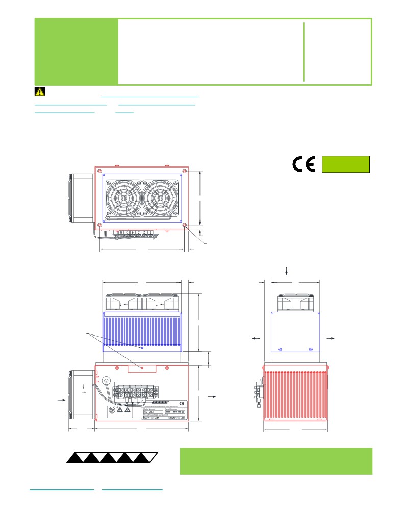
A 3D PDF, .stp, and .sldprt solid models
are also available from the website. Contact
88.9
TE Technology for 3D solid models in other
formats.
All dimensions in millimeters.
Internal (enclosure) side shown in blue;
External (ambient) side shown in red.
7.9
4X M5 x 0.8 - 6H THREADING 9.7 DEEP
139.7
6.35
INTERNAL
(ENCLOSURE)-SIDE
AIR FLOW INLET
130
11.2
10.8
80
25 DEEP HOLE with
95.6
INTERNAL
INTERNAL
M3 x 0.5 THREADING 9.7 DEEP
(ENCLOSURE)-SIDE
(ENCLOSURE)-SIDE
for SENSOR MOUNTING
AIR FLOW OUTLET
AIR FLOW OUTLET
21.9
EXTERNAL
EXTERNAL
(AMBIENT)-SIDE
(AMBIENT)-SIDE
AIR FLOW OUTLET
92.2
AIR FLOW INLET
Download manual
43.5
154
104.8
® Expert Engineering, Precision Manufacturing:
Quality Thermal Solutions Delivered
TE
TECHNOLOGY, INC.
NOTE: All specifications are subject to change without notice.
© 2018 TE Technology, Inc.
AC-053 6-FEB-2019 Page 2 of 9
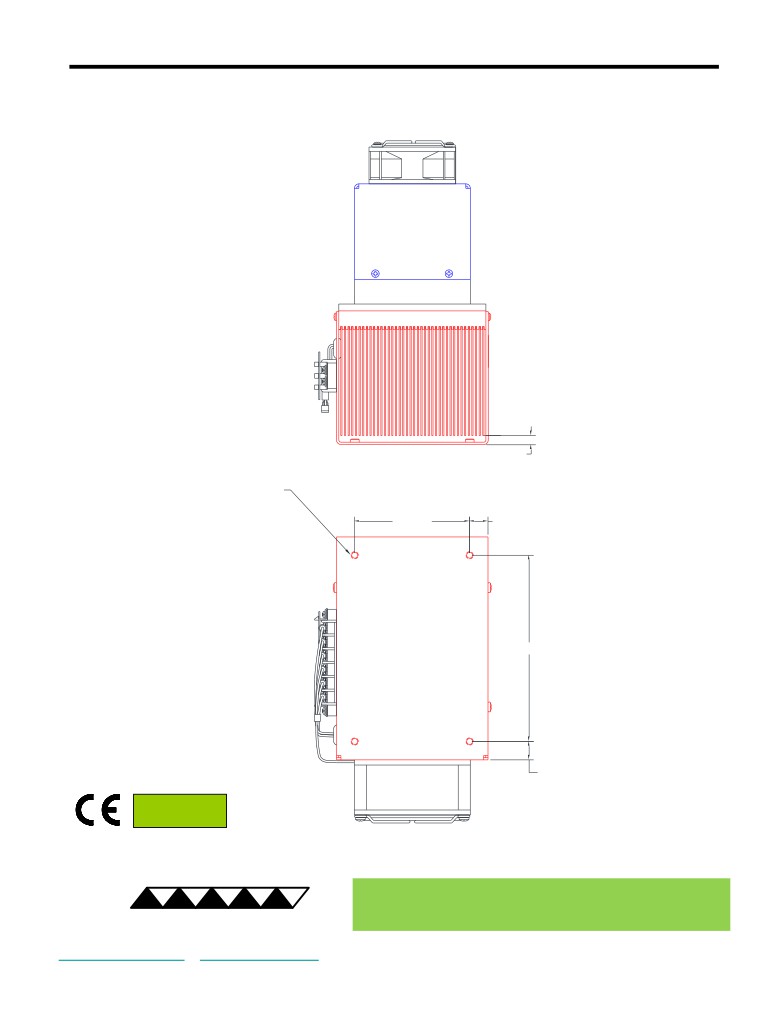
Bottom View of AC-053
Cooler can be mounted using the four M5 x 0.8 PEM nuts located as shown in the base of the shroud
6.3
4X M5 x 0.8 THREADED PEM NUT
2X 79.4
2X 12.7
2X 128.6
2X 12.7
RoHS Compliant
Directive 2011/65/EU
® Expert Engineering, Precision Manufacturing:
Quality Thermal Solutions Delivered
TE
TECHNOLOGY, INC.
NOTE: All specifications are subject to change without notice.
© 2018 TE Technology, Inc.
AC-053 6-FEB-2019 Page 3 of 9
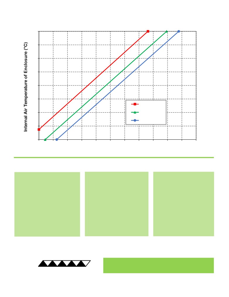
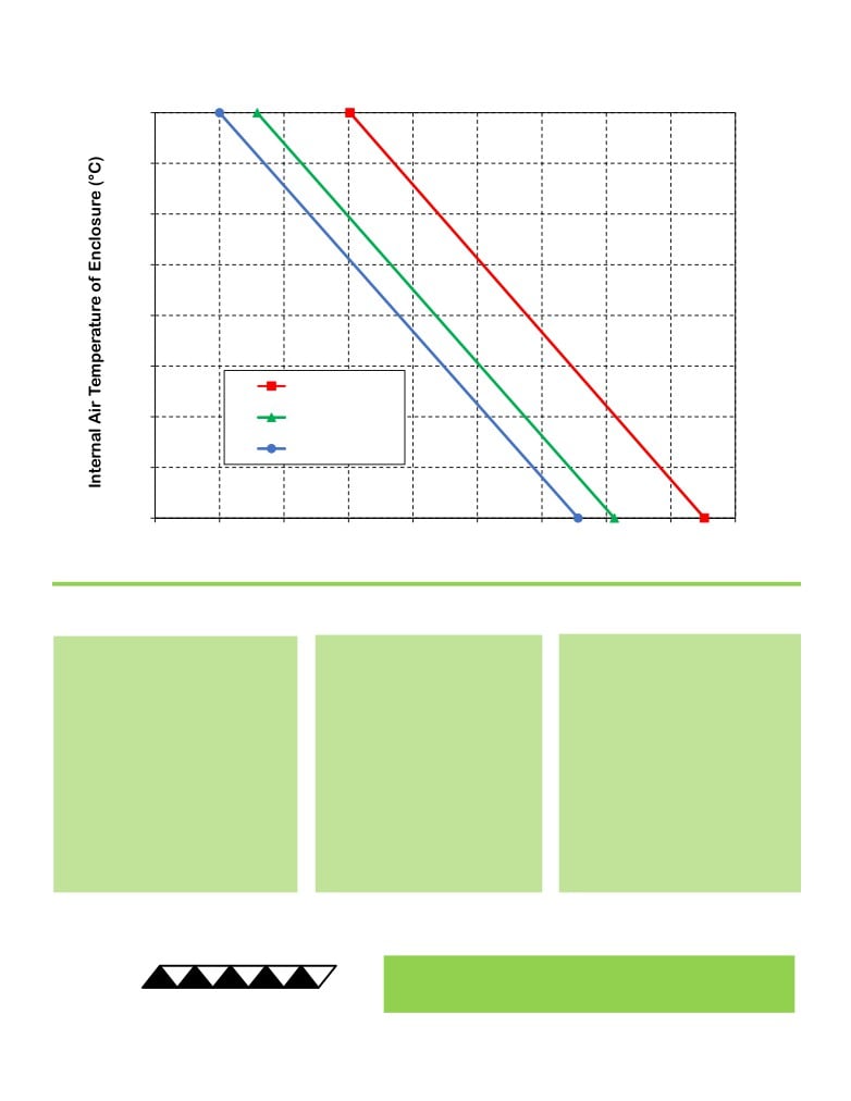
AC-053 Cooling Performance Graph
(removing heat from enclosure)
70
60
50
40
30
20
50 °C ambient
10
35 °C ambient
25 °C ambient
0
-10
0
10
20
30
40
50
60
70
80
90
100
110
Heat Removed from Enclosure (watts)
How to use the Performance Graph:
1. Select Performance Line
2. Select Enclosure Temperature
3. Determine Cooling Capacity
The diagonal lines represent cooling
Draw a horizontal line on the graph
The maximum amount of heat
performance at the indicated ambient
corresponding to the desired internal
that the cooler can remove from
air temperature (intake temperature
air temperature of the enclosure.
the enclosure is determined by
on the ambient-side fan). If the cooler
Make the line intersect with the
the intersection point (determined
is to operate at a different ambient,
performance line corresponding to
in the previous step). The cooler
then you must sketch in a new
the ambient temperature at which
will be able to maintain the
performance line. This can be drawn
the cooler is to operate.
desired enclosure temperature if
parallel to one of the existing lines,
the cooling capacity exceeds the
using the distance between the
heat load. If the heat load
existing lines as a scale to properly
exceeds the cooling capacity then
locate the new line.
a higher capacity cooler will be
needed.
Example: You need to maintain the enclosure at 15 °C while in a 25 °C ambient. The cooler can remove a maximum of
approximately 39 W of heat from the enclosure. If the heat load (internally generated heat plus the heat gain through
insulation, solar, vapor condensation, etc.) in the enclosure exceeds this, you would need more coolers and/or a larger
cooler.
® Expert Engineering, Precision Manufacturing:
Quality Thermal Solutions Delivered
TE
TECHNOLOGY, INC.
NOTE: All specifications are subject to change without notice.
© 2018 TE Technology, Inc.
AC-053 6-FEB-2019 Page 4 of 9
AC-053 Heating Performance Graph
(adding heat to enclosure)
70
60
50
40
30
20
25 °C ambient
10
0 °C ambient
-10 °C ambient
0
-10
40
60
80
100
120
140
160
180
200
220
Heat Added to Enclosure (watts)
How to use the Performance Graph:
1. Select Performance Line
2. Select Enclosure Temperature
3. Determine Heating Capacity
The diagonal lines represent heating
Draw a horizontal line on the graph
The maximum amount of heat that
performance at the indicated ambient
corresponding to the desired
the cooler can add to the enclosure
air temperature (intake temperature
internal air temperature of the
is determined by the intersection
on the ambient-side fan). If the cooler
enclosure. Make the line intersect
point (determined in previous step).
is to operate at a different ambient,
with the performance line
If the heat added to the enclosure
then you must sketch in a new
corresponding to the ambient
(including heat generated by
performance line. This can be drawn
temperature at which the cooler is
equipment inside) is greater than the
parallel to one of the existing lines,
to operate.
enclosure’s heat loss, then the
using the distance between the
cooler will be able to heat to the
existing lines as a scale to properly
desired temperature. A higher
locate the new line.
capacity cooler will be needed if the
total heat added is less than the
enclosure’s heat loss.
Example: You need to maintain the enclosure at 30 °C while in a -10 °C ambient. The cooler can add a maximum of
approximately 115 W of heat to the enclosure. If the heat dissipation from the enclosure exceeds this (plus anything
else generating heat), you would need more coolers and/or a larger cooler.
® Expert Engineering, Precision Manufacturing:
Quality Thermal Solutions Delivered
TE
TECHNOLOGY, INC.
NOTE: All specifications are subject to change without notice.
© 2018 TE Technology, Inc.
AC-053 6-FEB-2019 Page 5 of 9
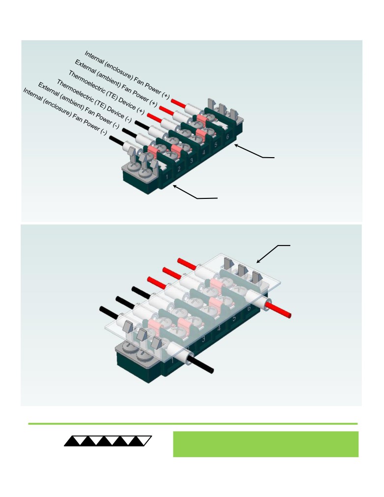
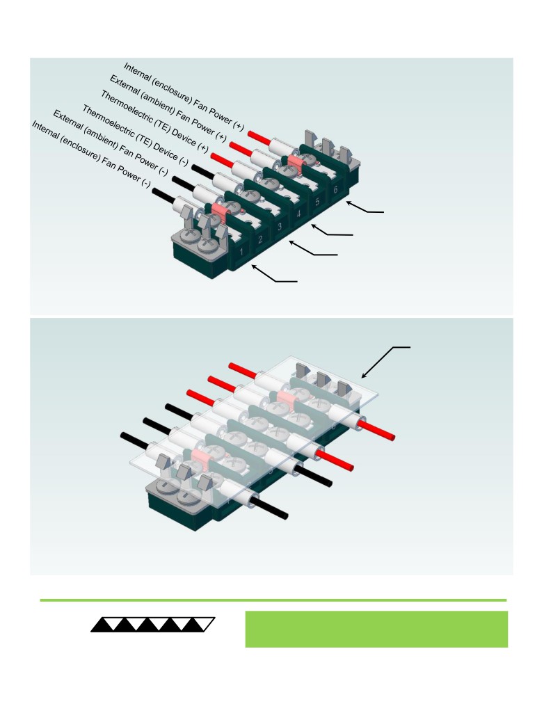
Terminal Block Configuration for Continuous Operation at Full Power
As-Shipped Configuration 1 of 2
1
REMOVE TERMINAL
BLOCK COVER
FOUR ELECTRICAL
JUMPERS INSTALLED
(ORIGINAL
CONFIGURATION)
2
LOOSEN TWO SCREWS
KEEP JUMPERS INSTALLED
® Expert Engineering, Precision Manufacturing:
Quality Thermal Solutions Delivered
TE
TECHNOLOGY, INC.
NOTE: All specifications are subject to change without notice.
© 2018 TE Technology, Inc.
AC-053 6-FEB-2019 Page 6 of 9
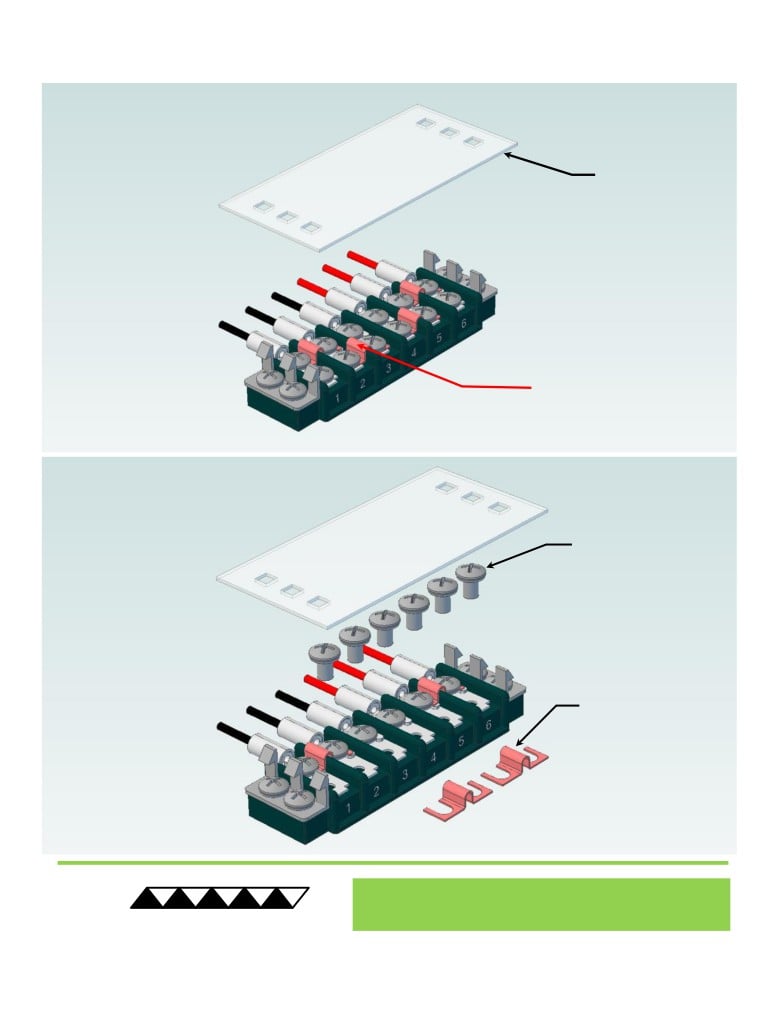
Terminal Block Configuration for Continuous Operation at Full Power
2 of 2
3
Power supply (+) Red Wire
to POSITION 6
Power supply (-) Black Wire
to POSITION 1
INSTALL WIRES,
4
TIGHTEN SCREWS
TO 1.0 N-M, AND
REPLACE COVER
® Expert Engineering, Precision Manufacturing:
Quality Thermal Solutions Delivered
TE
TECHNOLOGY, INC.
NOTE: All specifications are subject to change without notice.
© 2018 TE Technology, Inc.
AC-053 6-FEB-2019 Page 7 of 9
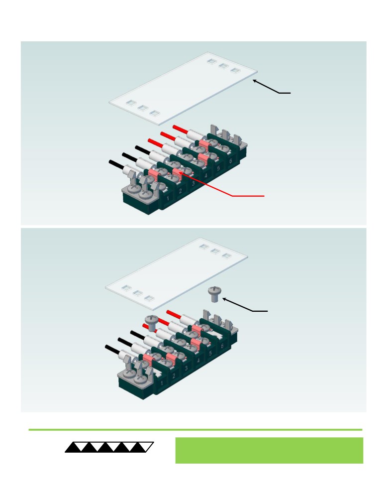
Terminal Block Configuration for Operation with Temperature Controller
1 of 2
1
REMOVE TERMINAL
BLOCK COVER
FOUR ELECTRICAL
JUMPERS INSTALLED
(ORIGINAL CONFIGURATION)
2
LOOSEN SIX SCREWS
REMOVE TWO
ELECTRICAL JUMPERS
FROM 2-3 AND 4-5
® Expert Engineering, Precision Manufacturing:
Quality Thermal Solutions Delivered
TE
TECHNOLOGY, INC.
NOTE: All specifications are subject to change without notice.
© 2018 TE Technology, Inc.
AC-053 6-FEB-2019 Page 8 of 9
Terminal Block Configuration for Operation with Temperature Controller
2 of 2
3
Power supply (+) Red Wire
to POSITION 6
Temperature Controller (+) Red Wire
to POSITION 4
Temperature Controller (-) Black Wire
To POSITION 3
Power supply (-) Black Wire
to POSITION 1
INSTALL WIRES,
4
TIGHTEN SCREWS
TO 1.0 N-M, AND
REPLACE COVER
® Expert Engineering, Precision Manufacturing:
Quality Thermal Solutions Delivered
TE
TECHNOLOGY, INC.
NOTE: All specifications are subject to change without notice.
© 2018 TE Technology, Inc.
AC-053 6-FEB-2019 Page 9 of 9